1. Overview and Necessity of Review on Surcharge Load
1) What is Surcharge Load?
In a typical scenario, the surcharge load acting on a tunnel is,
-
While the ground undergoes loosening due to tunnel excavation,
-
Soil or rock in the direction of gravity,
-
With a weight corresponding to each unit weight,
-
Vertically, or vertically and horizontally, and perpendicular to the structural elements,
represents the force acting.
2) Reasons for Calculating Surcharge Load
In KDS 27 40 05(2016), concrete lining is stipulated to "function as a structural element during its durable lifespan." Consequently, various loads, including rock loads, water pressure (or residual pressure), temperature loads, and rail loads, are considered in the analysis of the current tunnel structure to ensure the concrete lining performs its dynamic function as a structure.
Among these loads, surcharge load is a crucial design factor in the analysis of lining structures. Therefore, calculating surcharge loads before tunnel structure analysis is crucial, as it plays a significant role in the design process.
3) The Importance of Reviewing the Calculation of Surcharge Loads
To accurately calculate surcharge loads, an engineer must clearly establish the precise basis and reasons for their selection. This clarity is crucial for reducing errors during structural analysis and design, instilling confidence in one's own design, and facilitating a rational and reasonable design process.
Furthermore, there are various methods for selecting surcharge loads, each with its own approach and considerations.
-
Terzaghi's Rock Classification Method,
-
Numerical analysis,
-
The Q classification method, etc.
Because there are various calculation methods, it is necessary to accurately compare and understand them to derive a rational surcharge load calculation formula. Therefore, a thorough review is essential when calculating surcharge loads.
2. Overview of Surcharge Load Calculation Formulas
1) Empirical Surcharge Load Calculation Formula, Terzaghi Rock Classification Method (Rose, 1982)
Terzaghi first proposed a method for calculating rock loads in 1946. However, this method was specific to rock loads for tunnel linings and was later modified by Rose in 1982.
In the conventional NATM (New Austrian Tunneling Method), the installation of the primary lining occurs after tunnel excavation. As the tunnel is excavated, the surrounding ground experiences arching effects. To account for this, the rock classification method was modified by assuming that the range of ground loosening is limited to a certain extent after experiencing the arching effects.
.png?width=795&height=459&name=Modified%20rock%20load%20classification%20of%20Terzaghi%20(Rose%2c%201982).png)
Here, where b represents the tunnel width and m represents the tunnel height.
2) Surcharge Load Calculation Equation by Theoretical Equation, Terzaghi Theoretical Equation (Terzaghi, 1946)
Terzaghi also proposed an equation (1) assuming an arbitrary aspect of shear failure for dry, non-adhesive sandy soil and an equation (2) for the cohesive ground.
Equation (1) : Non-adhesive
%20%EC%A0%90%EC%B0%A9%EB%A0%A5%20%EB%AF%B8%EA%B3%A0%EB%A0%A4%EC%8B%9C.png?width=795&height=78&name=%EC%8B%9D(1)%20%EC%A0%90%EC%B0%A9%EB%A0%A5%20%EB%AF%B8%EA%B3%A0%EB%A0%A4%EC%8B%9C.png)
Equation (2) : Cohesive
%20%EC%A0%90%EC%B0%A9%EB%A0%A5%20%EA%B3%A0%EB%A0%A4%EC%8B%9C.png?width=795&height=78&name=%EC%8B%9D(2)%20%EC%A0%90%EC%B0%A9%EB%A0%A5%20%EA%B3%A0%EB%A0%A4%EC%8B%9C.png)
Here,
b = tunnel width, m = tunnel height, H = overburden depth, B = ground loosening range (m),
K = lateral pressure coefficient
%20%EC%A0%90%EC%B0%A9%EB%A0%A5%20%EA%B3%A0%EB%A0%A4%EC%8B%9C_%EC%97%AC%EA%B8%B0%EC%84%9C.png?width=795&height=95&name=%EC%8B%9D(2)%20%EC%A0%90%EC%B0%A9%EB%A0%A5%20%EA%B3%A0%EB%A0%A4%EC%8B%9C_%EC%97%AC%EA%B8%B0%EC%84%9C.png)
3) Surcharge Load Calculation Formula using RMR Value (Unal, 1983)
Unal proposed an empirical formula for calculating surcharge loads using the RMR value introduced by Bieniawski.
Particularly, the formula considers defining the height of the unstable zone of rock occurring from the tunnel excavation at the ceiling as the ground loosening height.

4) Surcharge Load Calculation Formula using Q-Value (Grimstad and Barton, 1993)
Barton established a boundary value of JCS (Joint Count System) 3 and proposed an empirical formula for calculating ground loosening based on different Q-values according to this boundary value.
The fundamental concept applied here is that rock movement varies based on the boundary value of JCS 3, serving as a benchmark for different rock behaviors.
-
Number of Sets ≥ 3

-
Number of Sets < 3

Here, where Q represents the Q-value, Jn is the number of set , and Jr is the roughness number of the joint surfaces.
5) Ease Load Calculation Equation Using Ground-Lining Interaction Model (G.L.I)
The ground-lining interaction model considers not only the construction process of installing the concrete lining but also a method that accounts for the load history within the ground. It conceptualizes the idea that the load acting on the primary support (1st lining) transfers to and is supported by the secondary support, which is the concrete lining (2nd lining).
In the scenario where the primary support loses its supporting capacity as a support structure, it is considered that the secondary support, the concrete lining, takes over and supports the load previously carried by the primary support.
%EC%9D%84%20%EC%9D%B4%EC%9A%A9%ED%95%9C%20%EC%9D%B4%EC%99%84%ED%95%98%EC%A4%91%20%EC%82%B0%EC%A0%95%EC%8B%9D.png?width=795&height=95&name=%EC%A7%80%EB%B0%98-%EB%9D%BC%EC%9D%B4%EB%8B%9D%20%EC%83%81%ED%98%B8%EC%9E%91%EC%9A%A9%20%EB%AA%A8%EB%8D%B8(G.L.I)%EC%9D%84%20%EC%9D%B4%EC%9A%A9%ED%95%9C%20%EC%9D%B4%EC%99%84%ED%95%98%EC%A4%91%20%EC%82%B0%EC%A0%95%EC%8B%9D.png)
%EC%9D%84%20%EC%9D%B4%EC%9A%A9%ED%95%9C%20%EC%9D%B4%EC%99%84%ED%95%98%EC%A4%91%20%EC%82%B0%EC%A0%95%EC%8B%9D_%EC%97%AC%EA%B8%B0%EC%84%9C.png?width=795&height=95&name=%EC%A7%80%EB%B0%98-%EB%9D%BC%EC%9D%B4%EB%8B%9D%20%EC%83%81%ED%98%B8%EC%9E%91%EC%9A%A9%20%EB%AA%A8%EB%8D%B8(G.L.I)%EC%9D%84%20%EC%9D%B4%EC%9A%A9%ED%95%9C%20%EC%9D%B4%EC%99%84%ED%95%98%EC%A4%91%20%EC%82%B0%EC%A0%95%EC%8B%9D_%EC%97%AC%EA%B8%B0%EC%84%9C.png)
h = tunnel height, b = tunnel width, γ = unit weight of the ground (kN/m3),
E = modulus of deformation (kN/m2)
3. An overview of the application of surcharge load
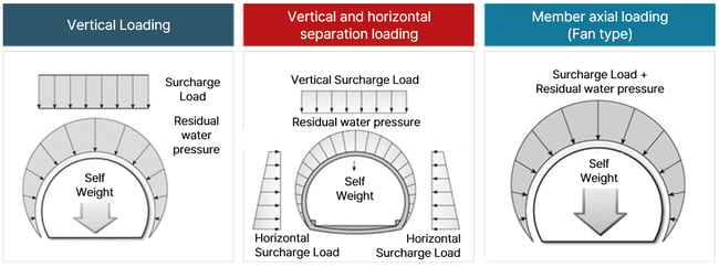
1) Vertical Surcharge Load Redistribution Method
For residual water pressure, the load is redistributed along the axis of the structural element.
However, for surcharge loads, the method involves calculating the load concentration using a formula and applying the load only within the width of the tunnel. It is crucial to ensure that when redistributing surcharge loads in the program, the "Projection" option is checked. This ensures that the load acting on the beam element is redistributed perpendicular to the direction of load application, considering the projected length of the beam element on the vertical line of action.
2) Vertical and Horizontal Surcharge Load Redistribution Method
For residual water pressure, the load is redistributed along the axis of the structural element.
However, for surcharge loads, the method involves calculating the load concentration using a formula. In this approach, vertical surcharge loads are redistributed within the width of the tunnel based on the calculated load height, and horizontal surcharge loads are redistributed in the horizontal direction. The horizontal surcharge load varies with the tunnel depth, so the load is redistributed with a constant increment based on this depth.
Just as before, when redistributing surcharge loads, it is crucial to check the "Projection" option.
3) Axial Surcharge Load Redistribution Method
Similar to redistributing residual water pressure, for surcharge loads, the method involves calculating the load concentration using a formula. In this case, the surcharge load is determined based on the calculated load height and is then redistributed along the axis of the structural element.
Since the load is redistributed along the axis of the structural element, there is no need to use the "Projection" option when redistributing the load.
4. Analysis of Midas Civil Structural Analysis Results according to Relaxation Load Application Method
1) Vertical surcharge load loading method
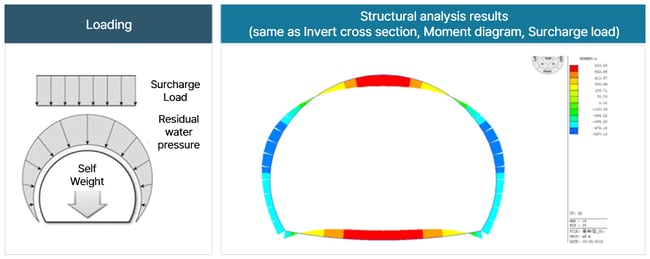
Maximum moment 633.63 kNm, tunnel perforation and floor maximum moment
2) Vertical and horizontal separation surcharge load loading method
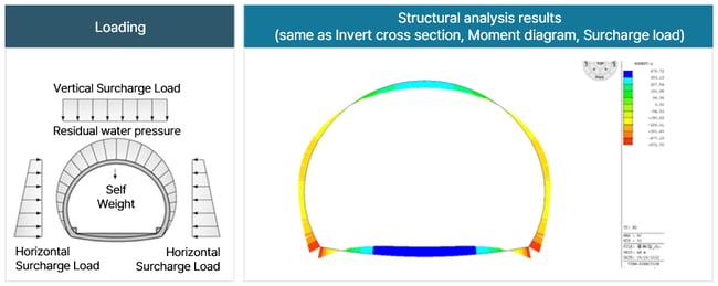
Maximum moment 572.78 kNm, lower end of tunnel sidewall (572.78) and bottom (478.72) maximum moment
3) Axial surcharge load loading method of member
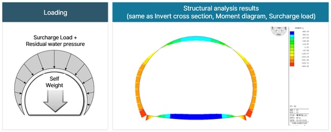
Maximum moment 453.99 kNm, lower end of tunnel sidewall (453.99) and bottom (440.09) maximum moment
4) Result
Depending on the surcharge load loading type acting on the member,
1) Vertical direction > 2) Vertical, horizontal direction > 3) Member axis direction
It was confirmed that the maximum moment occurred with the, and it can be seen that the tendency of moment occurrence is different.
References
-
Rose, D. (1982), “Revising Terzaghi’s tunnel rock load coefficient”, Proceedings of 23rd U.S Symposium on Rock Mechanics, AIME, New York, pp. 953-960.
-
Terzaghi, K. (1946), Introduction to tunnel geology in rock tunneling with steel supports, Commercial shearing and stamping company, Youngstown, Ohio.
-
Unal, E. (1983), Design guideline and roof control standards for coal mine roofs, Ph.D. Thesis, The Pennsylvania State University.
-
Grimstad, E., Barton, N. (1993), “Updating the Q-system for NMT”, Proceedings of int. symp. on sprayed concrete - modern use of wet mix sprayed concrete for underground support, Fagernes, Oslo, pp. 46-66.
-
Korea Institute of Construction Technology (2013), Study on Railway Construction Competitiveness - Tunnel Field - Final Report
/Steve%20Choi_346_240.png)
I'm Steve Choi, a tunnel structure engineer with a background from Seoul National University of Science and Technology, experienced in both specialized tunnel design and comprehensive engineering. Passionate about civil engineering, I seek collaborative innovation in tunnel and structural design within this community.
※ Click on the keywords below 'Topics' to view related content.