
How to Design Bridge Footing and Its Pile Spacing?
Example
In this example, we are designing a pile cap for a bridge. We have already calculated the forces at the top of the footing, but unclear of the footing dimensions along with the forces at its bottom face.
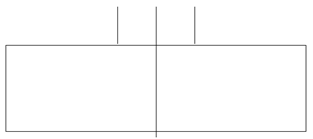
The factored forces at the footing top are given as Pu= 4212 kips, Vu longitudinal = 108.4 kips, Vu transverse = 112.4 kips, Mu Longitudinal = 7340 ft-kips, Mu transverse = 16480 ft-kips.
Pile capacity is given as φRn = 424 kips/EA. Also, we never want any uplift for the piles.
Step 1)
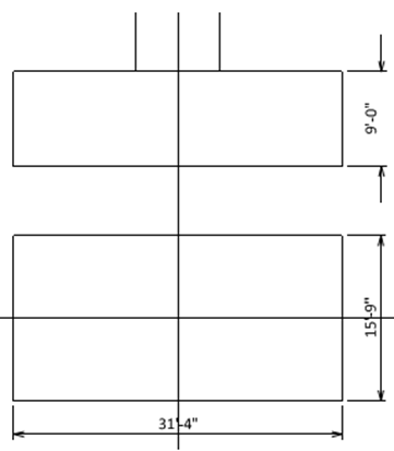
We have obtained these preliminary dimensions from engineering judgment or senior engineers' instinct.
Step 2) Calculating the forces at the footing bottom
Pu = 4212 kips + 1.25(31’-4”)(15’-9”){(0.150 kcf)(9’-0”) + (0.100kcf)(2’-0”)} = 5168 kips
M Long = (108.4 kips)(9’-0”) + 7340 ft-kips = 8316 ft-kips
M Trans = (112.4kips)(9’-0”) + 16480 ft-kips = 17492 ft-kips
Step 3) Find minimum required pile EA
%20Find%20minimum%20required%20pile%20EA.png?width=378&height=180&name=Step%203)%20Find%20minimum%20required%20pile%20EA.png)
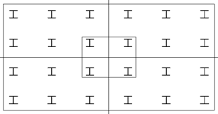
Try 6x4 = 24 EA,
Step 3)
Try transverse pile spacing x sps as 68”, which has been found from “Iteration” or “Optimization”.
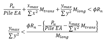
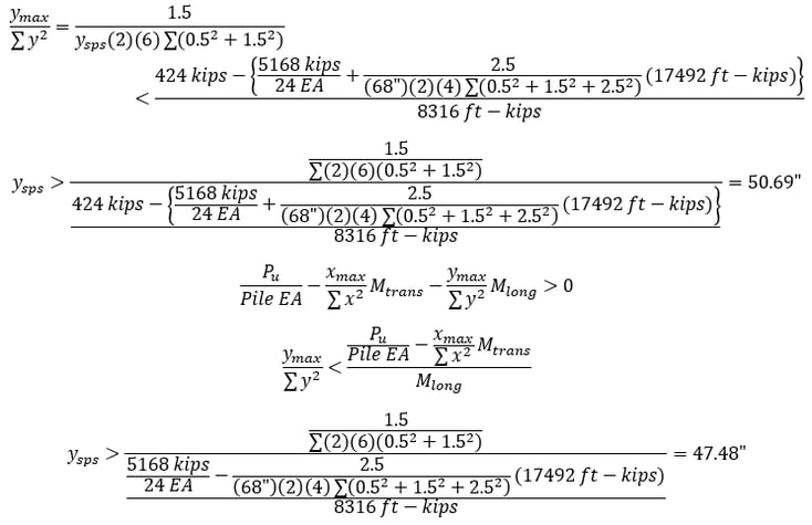
Therefore, the longitudinal pile spacing y sps is selected as 51”.
Step 4)
The pile cap dimension is b = (6EA-1)(68”) + 2(1’-6”) = 31’-4”, h = (4EA-1)(51”) + 2(1’-6”)’ = 15’-9”, which match with the assumed value. Otherwise, we have to “Iterate”.

What Are "Iteration" and "Optimization" in Pile Cap Design?
.png?width=624&height=455&name=Figure%205.%20Pile%20spacing%20vs%20Pile%20Cap%20Area%20(by%20program%20WSP%20USA-Pile).png)
The pile cap area from the dimensions obtained in Step 4 is (31’-4”) × (15’-9”) = 493.5 ft2.
This graph shows the pile cap area and corresponding y sps for each value of x sps. We can see that the trial value of x sps = 68” is the one to produce the minimum pile cap area, in other words, it is the “Optimum”. This value of x sps has never been assumed or guessed, but it was calculated by “Iteration”.
From the graph, we can see that x sps = 5’-0” to 6’-6” range also gives a very economical pile cap area. Some engineers prefer equal spacing for both directions, and x sps = y sps = 5’-0” would be a good choice for them.
The engineer can decide pile spacings easily from this graph.
Closure
Some engineers (including me) are obsessed with mathematical solutions and sometimes forget what is important. In the given figure, the x sps range 60” to 78” makes practically no difference, and trying to find the absolute minimum makes little sense. The engineer should try to determine the best pile spacing in the given range, rather than concentrate on small numbers.
We can solve this problem using the “Optimization” theory. We can ask the computer to find x sps and y sps which would give the minimum area of the pile cap, while the maximum reaction is less than φRn = 424 kips/EA
This methodology will be discussed later.
Here only the output from the “Optimization” theory is given: the “Optimum” pile cap dimension is x sps = 67.96”, y sps = 50.58”, and the pile cap area is 489.9 ft2., which is close to 493.5 ft2, we got from “Iteration”.
#Pile Cap Design
#Footing Dimensions
#Pile Spacing Optimization

He is a Senior Supervising Engineer with a high level of expertise in the design and analysis of suspension bridges. He has a solid fundamental understanding of structures and can apply his knowledge exceptionally well to the design and analysis of highly complex structures. He is also a strong communicator, able to identify and distill the key information that is relevant to the task at hand and present it in a clear and quickly understandable manner.