
4th-order differential equation
With his own solution, Moisseiff designed Manhattan bridge, main span 1480 ft, and opened in 1909.
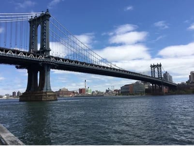
Although the main span of 1480 ft may not be impressive, the Manhattan Bridge is the first bridge designed by a non-linear theory and called the first modern suspension bridge.
With the success of the Manhattan Bridge, Moisseiff became confident with his solution and designed the George Washington Bridge, a main span of 3500 ft, which is more than twice the Manhattan bridge. The George Washington Bridge was opened in 1931 and is the first bridge with a main span of more than 1 km (3000 ft).
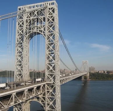
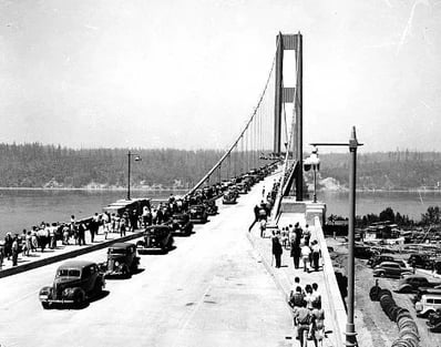
Upon the completion of these monumental bridges, Moisseiff garnered global recognition and proceeded to design additional suspension bridges. Ultimately, he conceived a remarkably slender plate girder suspension bridge, the Tacoma Narrows Bridge, the events of 1940 being well-known to all.
As previously discussed, it is not feasible to apply influence line analysis to deflection theory, as it requires numerous iterations to obtain a solution. Prior to the advent of computers, these calculations were labor-intensive and time-consuming, prompting many engineers to seek alternative methods for incorporating influence line analysis into suspension bridge design.
An Influence-Line Analysis for Suspension Bridges by D.J. Peery
Fortunately, D.J. Peery, a pioneering engineer, developed a solution to this challenge, as documented in his seminal work, "An Influence-Line Analysis for Suspension Bridges," published in ASCE Transactions in 1954. As previously noted, the deflection equation is as follows.
.jpg?width=290&height=50&name=Peery%20noticed%20that%20eq(2).jpg)
Peery noticed that eq(2) is just a beam formula with axial tension Hw+Hp, lateral point load p(x) and distributed load Hp(d2y/dx2).
Eq(2) can be rewritten into a more familiar form considering,
![Eq(2) can be rewritten into a more familiar form considering[1]](https://resource.midasuser.com/hs-fs/hubfs/MOTIVE_Image/Expert%20Tip%20Analysis%20of%20Suspension%20Bridges%203/Eq(2)%20can%20be%20rewritten%20into%20a%20more%20familiar%20form%20considering%5B1%5D.jpg?width=90&height=47&name=Eq(2)%20can%20be%20rewritten%20into%20a%20more%20familiar%20form%20considering%5B1%5D.jpg)
![Eq(2) can be rewritten into a more familiar form considering[2]](https://resource.midasuser.com/hs-fs/hubfs/MOTIVE_Image/Expert%20Tip%20Analysis%20of%20Suspension%20Bridges%203/Eq(2)%20can%20be%20rewritten%20into%20a%20more%20familiar%20form%20considering%5B2%5D.jpg?width=387&height=72&name=Eq(2)%20can%20be%20rewritten%20into%20a%20more%20familiar%20form%20considering%5B2%5D.jpg)
If Hw+Hp is constant (or if we can assume to be constant), eq(24) can be separated into two formulars.
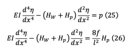
Equations (25) and (26) can be solved for any given value of p and Hp. These equations are commonly used in beam-column analysis, and solutions have already been established by our predecessors, as documented in Timoshenko's Theory of Elastic Stability. By utilizing equation (25) and setting p equal to 1, we can derive the moment equations.
Timoshenko's Theory of Elastic Stability
=0.jpg?width=288&height=109&name=At%20x=0%20and%20x=L%2c%20deflection%20%CE%B7(x)=0.jpg)
At x=0 and x=L, deflection η(x)=0, cable coordinates from pylon top y(x)=0, and moments as a simple beam M0(x)=0. From these conditions,
%2c%20for%20unit%20value%20of%20Hp=1.jpg?width=345&height=121&name=From%20eq(26)%2c%20for%20unit%20value%20of%20Hp=1.jpg)
From eq(26), for unit value of Hp=1, the moment and deflection equations are
%2c%20the%20influence%20line%20for%20Hp%20can%20be%20written.jpg?width=533&height=121&name=From%20eq(30)%2c%20the%20influence%20line%20for%20Hp%20can%20be%20written.jpg)
From eq(30), the influence line for Hp can be written as
%2c%20the%20integral%20term-1.jpg?width=363&height=68&name=In%20eq(31)%2c%20the%20integral%20term-1.jpg)
In eq(31), the integral term is
%20is%20a%20dimensionless%20term%20and%20can%20be%20calculated%20easily%20with%20a%20given%20value.jpg?width=573&height=67&name=Eq(32)%20is%20a%20dimensionless%20term%20and%20can%20be%20calculated%20easily%20with%20a%20given%20value.jpg)
Eq(32) is a dimensionless term and can be calculated easily with a given value of cl.
From eq(27),(28),(29),(31), influence line for girder moment can be written as

Effects from temperature changes can be considered separately and can be added to the influence line analysis results.
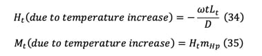
We can calculate influence lines for two extreme values of cable tensions Hw and Hw+Hp max. We can calculate two sets of girder moments, shears, deflections, etc., and then find the final value from interpolation.
The interpolation for cable tension forces can be done by following methods (Kawada, Analysis of suspension bridges by influence lines).
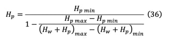
The calculation is very systematic and elegant. Let’s find M(x/L=0.2) with the same example.
![The calculation is very systematic and elegant[table]](https://resource.midasuser.com/hs-fs/hubfs/MOTIVE_Image/Expert%20Tip%20Analysis%20of%20Suspension%20Bridges%203/The%20calculation%20is%20very%20systematic%20and%20elegant%5Btable%5D.jpg?width=605&height=186&name=The%20calculation%20is%20very%20systematic%20and%20elegant%5Btable%5D.jpg)
![The calculation is very systematic and elegant[equation]](https://resource.midasuser.com/hs-fs/hubfs/MOTIVE_Image/Expert%20Tip%20Analysis%20of%20Suspension%20Bridges%203/The%20calculation%20is%20very%20systematic%20and%20elegant%5Bequation%5D.jpg?width=261&height=59&name=The%20calculation%20is%20very%20systematic%20and%20elegant%5Bequation%5D.jpg)
Center span
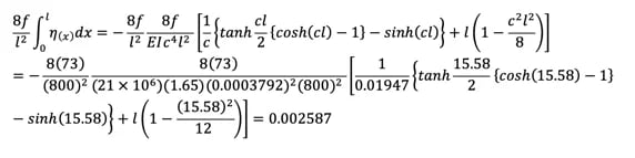
Side span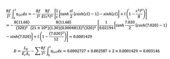
Influence lines for Hp are as follows:
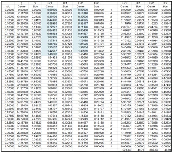
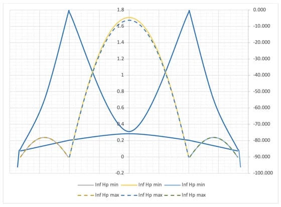
The area of the influence line can be calculated easily using Simpson’s methods.
Cable tension increase Hp for (Hw+Hp) min case is
%20min%20case.jpg?width=511&height=73&name=Cable%20tension%20increase%20Hp%20for%20(Hw+Hp)%20min%20case.jpg)
Now we found the maximum Hw+Hp=13140+2586=15730 ton and can find the influence line for girder moment as follows.
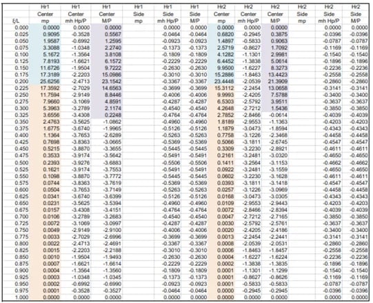
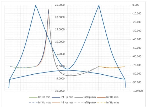
We can find two sets of girder moments at x=0.2L for each value cable tension Hw and Hw+Hp max. The summary is as below.
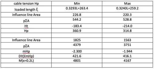
The final girder moment is
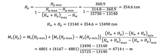
The moment M(x/L=0.2) of 4714 t-m at this juncture is in close proximity to the moment obtained from the deflection theory, which is M(x/L=0.2) = 4707 t-m, with a negligible error of 0.1%. In the scenario of the (Hw+Hp) min case, the girder stiffness is underestimated, resulting in a slightly conservative moment (with an error of 2%, which is deemed sufficient for practical design). In the author's opinion, the (Hw+Hp) min case can be utilized solely for preliminary design purposes. Lastly, a comparison of the girder moments is presented.
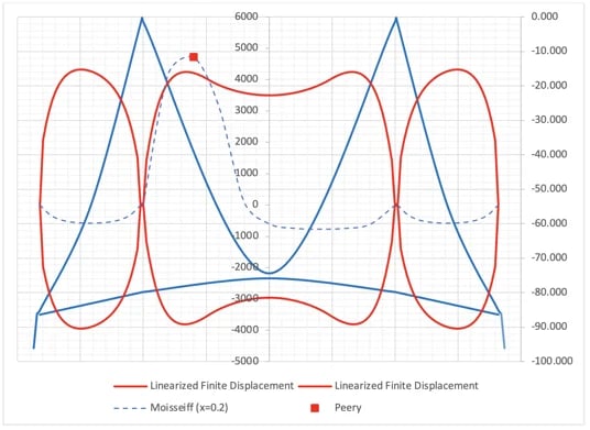
Girder moment comparison

He is a Senior Supervising Engineer with a high level of expertise in the design and analysis of suspension bridges. He has a solid fundamental understanding of structures and can apply his knowledge exceptionally well to the design and analysis of highly complex structures. He is also a strong communicator, able to identify and distill the key information that is relevant to the task at hand and present it in a clear and quickly understandable manner.