The Question
We have structural analysis programs. Can we make the model (like other conventional bridges) and perform the analysis (as usual)?
The Answer
The short answer is yes, we can!
But the results may be useless. The scary parts of FEM are it gives results without any warning/error message, but the output may not be correct or useless.
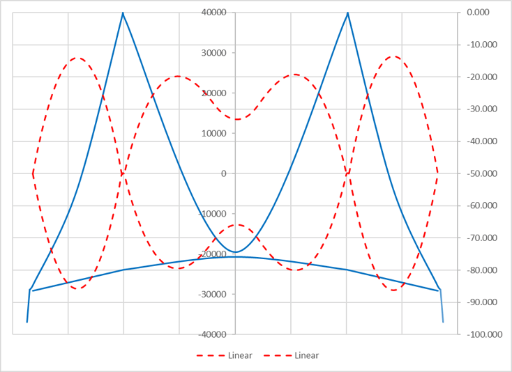
Fig1 shows girder moments due to live loads for a medium-span suspension bridge. The main span is around 2600 ft (now the longest one was built by Turkish engineers, and the main span, between pylon to pylon, is 6600ft, much more than a mile!). This example bridge is not a real one and was proposed by Dr. Hirai for comparison (Steel Bridge III, by Hiral Atsushi).
We can analyze suspension bridges in a conventional way. However, the output moment is too big, and we cannot design the section. From conventional linear analysis (dashed line), we got a moment around 29,000 t-m at the center of the side span. Moment 29,000 t-m is huge and not easy to design for this moment. This is one of the main reasons why we couldn’t design a long-span suspension bridge in the 19th century, and the span limit was around 2,000 ft.

If you have hawk’s eyes, you can see that the girders are somewhat stocky for these traditional suspension bridges in the 19th century.
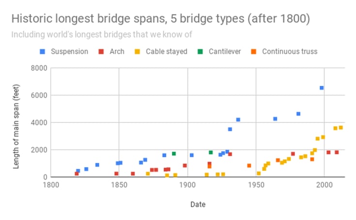
As can be seen from Fig3, somewhere in the 1930s, the bridge span went up dramatically, approximately twice. What has happened in these eras?
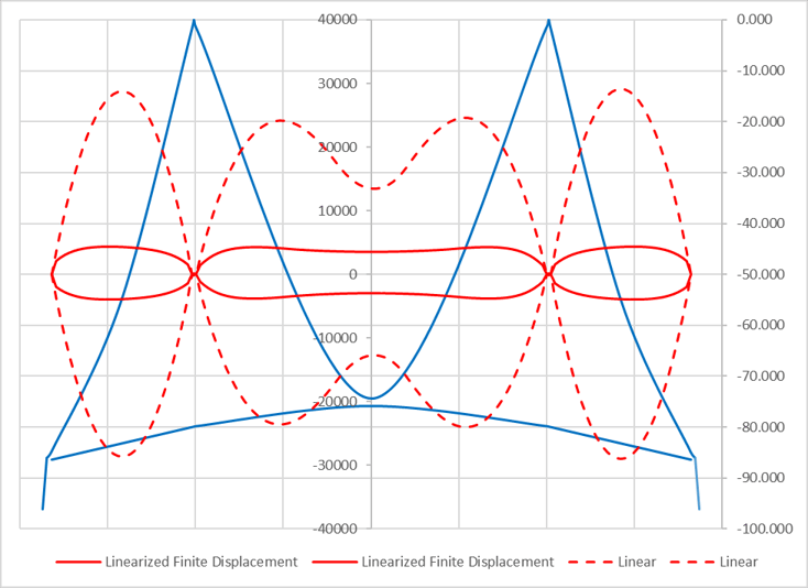
If we consider some kinds of non-linearity (red solid line), even a very simple one like linearized finite displacement methods, the moment will drop down to 4,300 t-m, and we are much more comfortable designing the girder section.

You can check more of these details in the download file.
How is this possible?
An example

He is a Senior Supervising Engineer with a high level of expertise in the design and analysis of suspension bridges. He has a solid fundamental understanding of structures and can apply his knowledge exceptionally well to the design and analysis of highly complex structures. He is also a strong communicator, able to identify and distill the key information that is relevant to the task at hand and present it in a clear and quickly understandable manner.