Bridge

Substructures

1. What is Substructure?

As shown in the figure below, there are many different types and forms of Substructures, and the design and analysis methods vary accordingly. However, each type and form of substructure is intended to withstand the load transmitted from the superstructure while allowing the bridge to be constructed at the desired height (design level).

The substructure is determined by considering the type of superstructure, construction method, ground conditions, and aesthetic factors. Conversely, the layout plan of the substructure, according to the surrounding roads or ground conditions, is the biggest factor in determining the span length of the superstructure. Therefore, instead of planning the two parts separately, the whole structure should be reviewed and planned as one system.
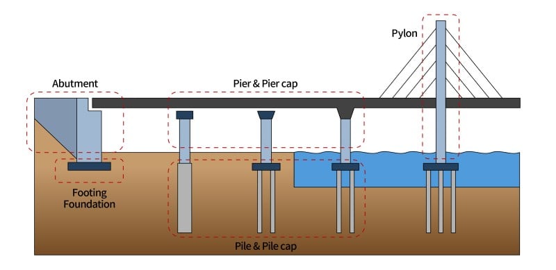
  • Fig. Types of substructures for bridges

Substructures can be classified into piers (columns), foundations (footings), and abutments.

Since the loads acting on each structure are different, each should be designed for various load types and load combinations based on the design criteria. The different types of substructures are described below.

2. Description of Abutments

An abutment is a structure that is installed at the beginning and end of the bridge to support the superstructure. It connects roads or railroads to bridges, and in order to do so, earthwork sections are needed at the location where the road ends (the position at which the bridge starts).

  • Fig. Bridge abutment

The names of each part of the abutment are shown in the figure below. The body of the abutment is composed of a stemwall and a backwall. The backwall supports the earth pressure of the backfill and the live load passing over the abutment. The bracket (corbel) connected to the backwall plays the role of supporting the approach slab. Brackets are frequently designed for flexure, but in some cases, they must be designed as a Strut-and-Tie Model (STM) according to the design standards.

  • Fig. Abutment components

The stemwall is responsible of resisting the earth pressure as well as the load transmitted through the bearing. Foundations (footing) are then responsible of transferring all the loads to the ground or piles. In the case of spread foundations, certain criteria for external stability such as overturning, sliding, and settlement must be considered.

  • Fig. Types of instability failure of abutment

The loads transmitted from the superstructure to the abutment are transmitted through the bearing. When bearings are not present, the superstructure and abutment are integrated together, and these types of bridges are referred to as integral bridges (integral abutment bridge).

The loads used in the design of abutments include the reactions transferred from the superstructure to the bearing, horizontal earth pressures, live loads, and surcharge loads. The material present behind the bridge is called the backfill. Horizontal earth pressure occurs according to the type of backfill and the height of the structure.

  • Fig. Loads for abutment design

The horizontal earth pressure should be calculated according to the design criteria, and the static earth pressure and seismic earth pressure should be considered respectively. The calculation method for seismic earth pressure differs for each design standard; therefore, each design standard must be carefully considered. The simplified calculation methods proposed by AASHTO and the Eurocode are as follows: Section 11, Appendix A11 of the AASHTO provides a description of the Mononobe-Okabe method applicable to seismic design. The Eurocode provides the “Simplified Analysis for Retaining Structures” in EN 1998-5 Annex E, and the calculation method provided here is also based on the Mononobe-Okabe method.

3. Types of Piers & Pier Caps

Piers (columns) are structures that support the superstructure, and are used for bridges with two or more spans. The superstructure loads are transmitted through the bearings and pier caps, but in some cases, the pier caps and the superstructure are integrated together with no bearings (integral pier bridges).
Various types of piers and pier heads can be combined depending on the type of superstructure, construction method, adjacent road conditions, and ground conditions. Some representative types of piers and pier caps are shown below:

A. Hammerhead Pier

The figure below shows an example of a hammerhead pier, a type commonly used for single piers (single columns). It is also commonly referred to as a T-type pier or tapered pier cap, and is widely used because it’s both economical and has good workability.

  • Fig. Hammerhead pier

In order to enhance the aesthetic factor, pier caps are designed with curves. These types of piers are referred to as Torch piers or pier caps with parabolic haunches. Although the aesthetic factor improves, the construction factor becomes extremely difficult.

  • Fig. Pier cap with parabolic haunches

Asymmetric cantilever piers are sometimes used when the location of the piers cannot be centered on the bridge due to existing roads or obstacles.

  • Fig. Cantilever pier (cantilever pier cap)

B. Rigid Frame Pier

Rigid Frame piers are used when bridges are wide or when piers must be installed to avoid obstacles such as roads. Multi columns are installed on one foundation or on each foundation.

  • Fig. Rigid frame pier

C. Solid Wall Pier

Solid wall piers are used for very large and tall bridges. They provide good structural resistance, but are not economical and are difficult to construct.

  • Fig. Solid wall pier

Additionally, many types of piers are used in consideration of the site situations and aesthetics.
Flexural design is typically used for pier caps, but depending on the design standards, the Strut-and-Time Model (STM) can be applied.

  • Fig. Strut-and-Tie model for pier cap

4. Description of Foundation

The loads transmitted from the superstructure and the self-weight of the piers and pier caps are transmitted to the foundations. The most commonly used foundations in bridges are spread foundations (spread footing) and pile foundations (deep foundation). The foundations are determined by the size of the bridge, but the ground conditions have the greatest impact.

Pile foundations can be divided into monopoles, which are a combination of single columns and single piles, and group piles with pile caps. Since each structure has different behaviors and vulnerabilities, the design must be carried out according to the design criteria. Cover and reinforcement details, especially the confinement, must be carefully checked because it varies depending on the type of pile, material used, and design standards.
If the pile foundation is included in the structural analysis, the boundary condition should consider the soil-structure interaction.

Flexural design is typically used for pile caps, but in some cases, the Strut-and-Tie Model (STM), were pile head reactions or pier bottom forces are obtained through global analysis, is used. STM of pile caps is designed for 2D STM by separating longitudinal and horizontal directions, but for accurate calculations, 3D STM is required.

  • Fig. Strut-and-Tie model for pile cap

콘텐츠가 도움이 되셨나요? Did you find the content helpful?
To List
Table of Contents

Stay Updated on bridge Issues.