Wood Armer Moments for Skew Slabs
Please fill out the Download Section (Click here) below the Comment Section to download the Ebook!
Table of Contents
1. Introduction
2. Wood Armer Moments
3. Midas Civil Features for Wood Armer Moments
4. Verification of Wood Armer Moments
1. Introduction
A bridge deck configuration depends upon the site conditions and road alignment. This article will discuss how to calculate the design moments along the reinforcement directions in a skew slab. Slab bridges tend to span in a direction running from support to support. As skew increases, the moments vary towards edges, maximum at the obtuse end and minimum towards the acute end. These can be seen from the moment contours, as shown in Figure 1. Various parametric study results have indicated that shear forces and bending moments increase with increasing skew angle.
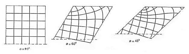
There are many theoretical approaches to obtain optimum reinforcement angles for the most economical design for different skew angles in a slab. However, such theoretical optimization techniques are usually not practical and may not be economical to execute. A few of the different possible layouts for a skew bridge are shown in Figure 2. One can create the meshing as per different configurations such as parallel to skew, transversely normal, and longitudinally normal type of meshing. Each has some variations depending upon the loadings.

It is observed that as the skew increases:
1. The deflection reduces
2. The longitudinal moment reduces
3. The point of maximum longitudinal moment shift towards the obtuse corner
4. The shear force concentrate at the obtuse corner
5. The transverse moment increases
The layout with straight bars in a skew slab is not the most practical. Research on skew deck slab has shown that an orthogonal layout is optimized most of the time and deviates to provide the higher amount of reinforcement.
Several parameters can affect the magnitude of moments at the obtuse corner
1. structural continuity
2. geometry of the slab
3. Cracked conditions
4. Loading
2. Wood Armer Moments
The design moments along the reinforcement for the skew slab are a combination of (a) normal bending moments and a torsional component. These are called wood armer moments. The Wood-Armer equations were derived for the design of skew as well as curved reinforced concrete slabs.
3. Midas Civil Features for Wood Armer Moments
To calculate the wood armer moments in midas Civil, we need to generate the slabs as plate elements. From there, we need to define the domain and sub-domain to provide the reinforcement directions along to which these forces need to arrive. A Sub-Domain can be defined while a mesh is generated using the Auto mesh feature in midas Civil or it can also be defined from the Define Sub-Domain.
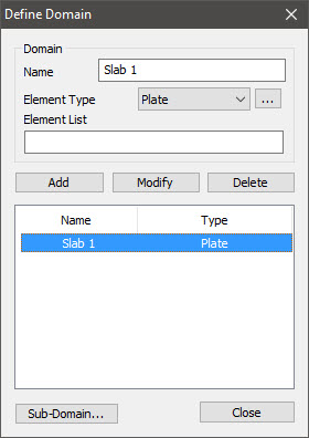 Figure 3. Domain definitions in midas Civil
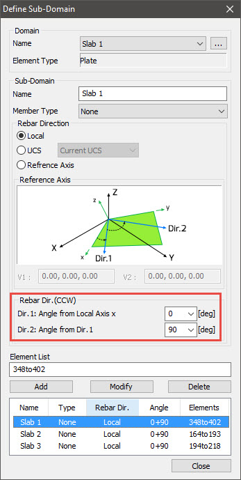 Figure 4. Sub-domain definition in midas Civil
The reference axis used to define the rebar direction can be: (Refer to Figure 3&4)
1. Local
2. UCS
3. Reference Axis
1. Local: We can define the rebar direction along the Local Coordinate System of the plate elements.
2. UCS: We can define the rebar direction along the User-defined Coordinate System. If user-defined coordinates are not specified, the Global Coordinate System can be used.
3. Reference Axis: We can define the rebar direction along the user-defined Reference Axis. Here we need two nodes for V1 to be specified to define the x-direction from the origin of the coordinate system. Then V2 is selected to decide the plane, and z-direction is selected as per ‘Right-Hand’ rule.
4. Moment Calculations in midas Civil
From the midas Civil analysis results, the following plate moments about the local axis are obtained:
- mxx
- myy
- mxy
In order to calculate design forces or wood armer moments in the reinforcement direction, angle α and φ will be taken as shown in Figure 5.
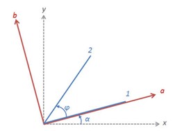 Figure 5. Domain and sub-domain definitions in midas Civil.
where,
x, y: the local axis of the plate element.
1, 2: the reinforcement direction.
α: the angle between local x-direction and rebar direction 1.
φ: angle between rebar direction 1 and rebar direction 2.
First, the internal forces (mxx, myy and mxy) are calculated into a-b coordinate system as shown in fig. 5.
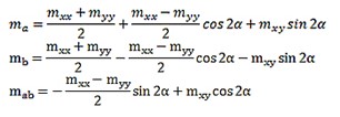
Then, Wood-Armer moments are calculated as follows:
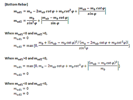
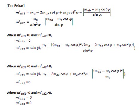
where,
mud1 : is the initial moments in direction 1
mud2 : is the initial moments in direction 2
m’ud1 : is the wood armer moments in direction 1
m’ud2 : is the wood armer moments in direction 2
5. Verification of Wood Armer Moments
A verification of Wood Armer Moment with manual calculations is explained here.
Consider case 3 for verification purposes. To understand the calculations, we will consider node number 96, which has a maximum moment; refer to fig.6.
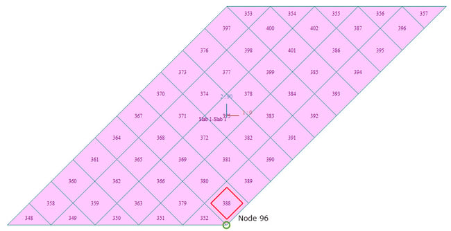 Figure 7. Reference element for verification.
Manual Calculations for Wood Armer Moments
Local forces from the analysis are listed here: (Refer to Figure 8)
Element number = 388;
Node Number = 96;
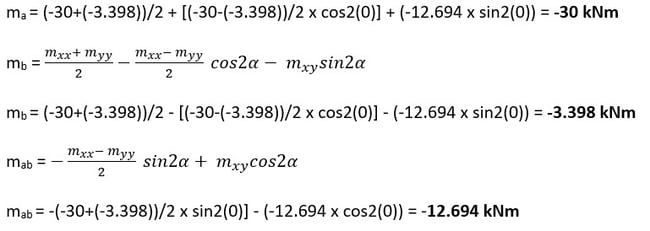
Mxx = -30 kNm;
Myy = -3.398 kNm;
Mxy = -12.694 kNm;
Skew angle = 45◦;
Reinforcement Direction 1 = 0◦ from local axis x;
Reinforcement Direction 2 = 90◦ from local axis x
 Figure 8. Plate local forces in midas Civil
Reinforcement Angle α = 0◦ = 0 x (π/180) = 0 rad;
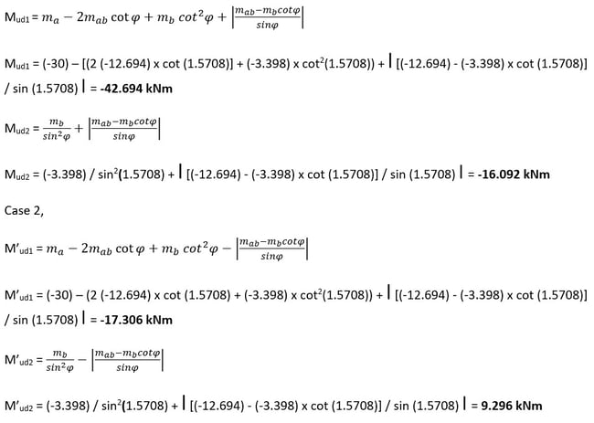
and φ = 90◦ = 90 x (π/180) = 1.5708 rad;
Member force about Angle α)

Member force about Angle φ
Top Design Force
As, M’ud1 < 0 and M’ud2 < 0,
M’ud1 = 42.694 kNm
M’ud2 = 16.092 kNm
Bottom Design Force
As M’ud1 > 0 and M’ud2 > 0,
M’ud1 = 0 kNm
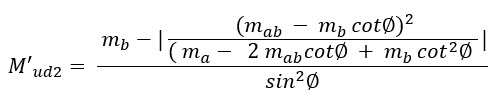
M’ud2 = (-3.398) – l (-12.694 – (-3.398) x cot2 (1.5708)) / (-30 – 2 x -12.694 x cot (1.5708)) + (-3.398 x cot2 (1.5708)) l = 1.97325 kNm
|
Wood Armer Moments |
Manual Calculations |
Midas Civil |
||
|
Direction |
Direction 1 |
Direction 2 |
Direction 1 |
Direction 2 |
|
Top |
42.694 |
16.093 |
42.694 |
16.093 |
|
Bottom |
0 |
1.973 |
0 |
1.973 |
Table 1. Comparison of Wood Armer Moments from manual calculations and midas Civil.
The Wood Armer Moments in each directions calculated by from the Empirical formulae can be validated with midas Civil output as shown in the table 1.

/Photos%20of%20specialists/Pratap-1.png)