Please fill out the Download Section (Click here) below the Comment Section to download the Full Webinar PDF File
In this webinar, we will introduce the midas Civil application of the transverse analysis of prestressed concrete box girder in the cable-stayed bridge.
This case study highlights
1. Modeling Concept
2. Considered Load Case with Functions in midas Civil
3. Considered Boundary Conditions with Functions in midas Civil
4. Post-processing and Other Modeling Applications
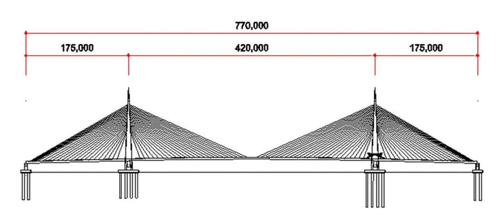
The example structure below is the Saemangeum bridge in South Korea. This project is a preliminary design. The structure is a cable-stayed bridge with concrete superstructures, pylons, and piers. The superstructure is composed of pre-stressed concrete girders. The transverse analysis was carried out in midas Civil.
1. Modeling Concept
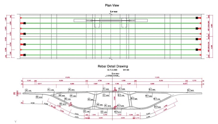
- 3D Plate elements model.
- 3 types of sections were considered in the same element shape.
- Lateral tendon prestressed loads using tendon profiles were considered.
- Related functions of midas Civil : Import > Auto CAD dxf, Extrude, Translate, Thickness Property with Offset option.
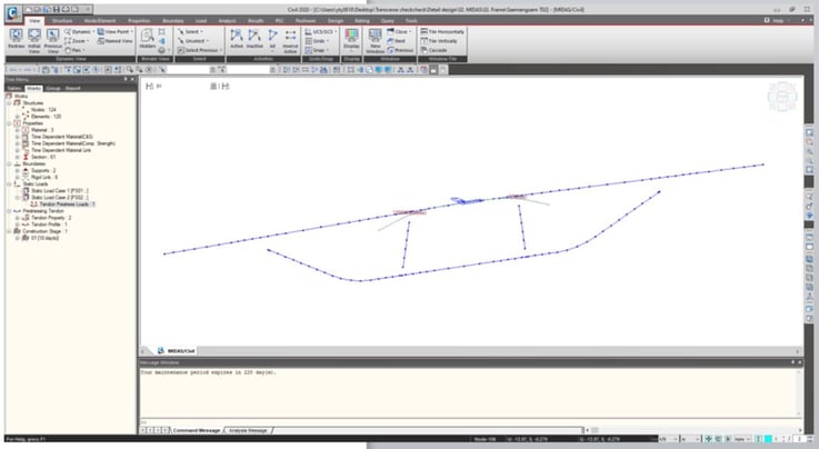
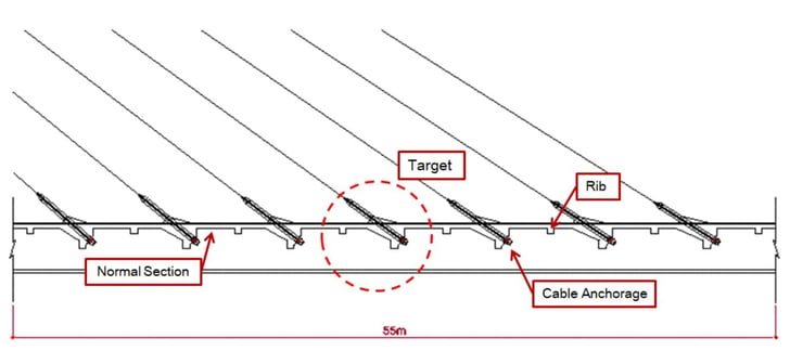 Fig 3. Longitudinal View of Target Model
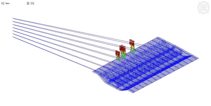 Fig 4. 3D plate elements model for the PSC girder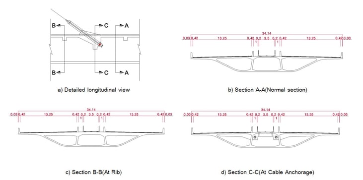
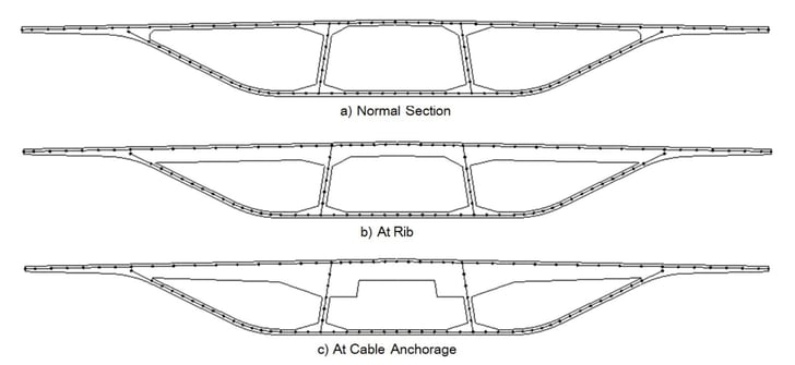
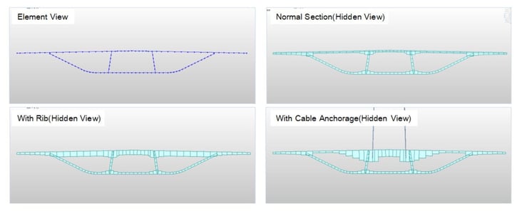 Fig 7. Plate elements with offset options
2. Load Cases with Functions in midas Civil
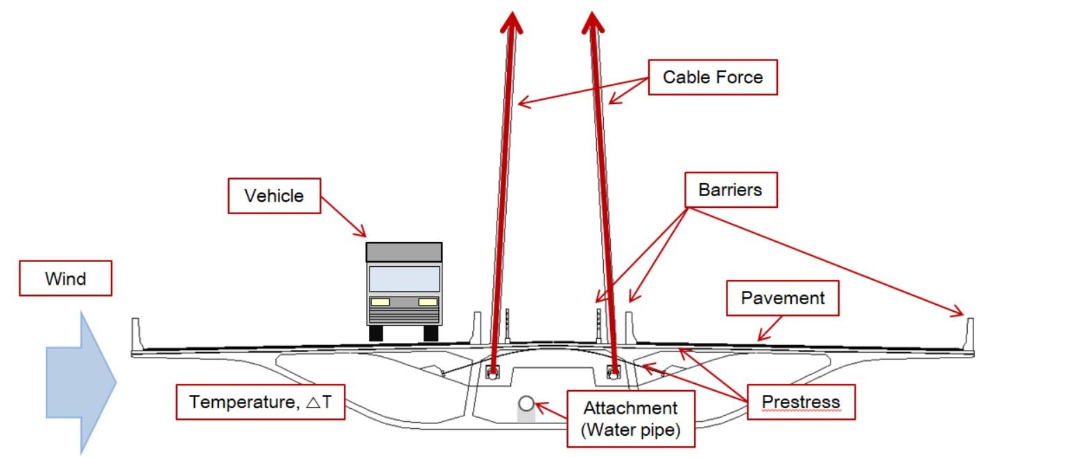
- This model tried to have all conditions around the structure to get better results.
- Considered conditions are shown below.
- Functions in midas Civil are shown in bold letters
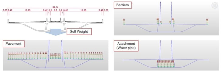
2.1. Self-weight load of the girder & Superimposed load
- Self Weight function was used.
- Plane Loads function was used for superimposed loads.
2.2. Wind load
- Nodal Load function was used for the wind force on the barriers which are not modeled as elements.
- Pressure Load function was used for the wind force on the side of the girder.
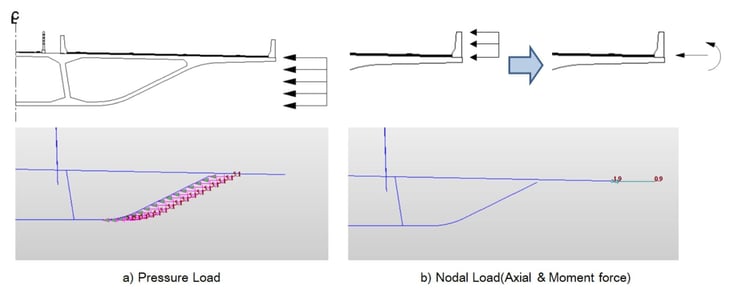 Fig 10. Wind loads
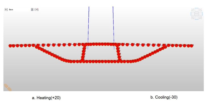
2.3. Temperature load
- Element Temperature function was used for cooling and heating cases of the uniform temperature.
2.4. Prestressed load
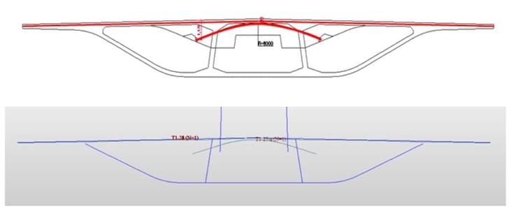
- Tendon Prestressed Load function was used.
- Tendon Profile function was used to check the effect of the profile.
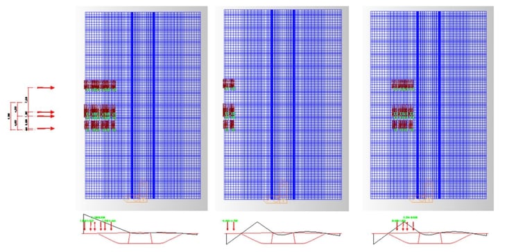
2.5. Vehicle load
- Plane Load function was used.
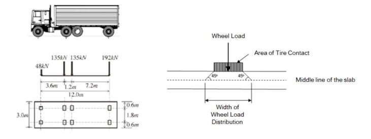
- A vehicle is a truck. Wheel Loads of a truck is used.
- The concentrated load of wheels is replaced with the distributed load.
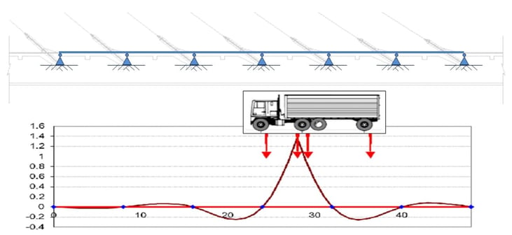
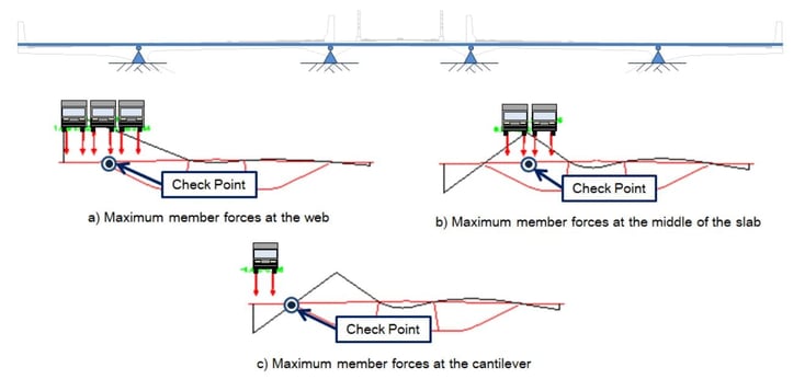
- In order to get critical positions of the vehicle, the influence diagrams were considered in the longitudinal and transverse directions.
2.6. Cable force
- Pretension Loads function was used.
- Truss elements were used for cables to consider the cable force only.
- In another approach, Point Spring boundary condition with its stiffness can be used instead of modeling cables.
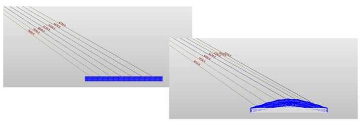 Fig 17. Cable Force: Pretension loads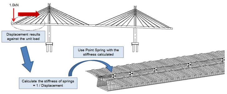
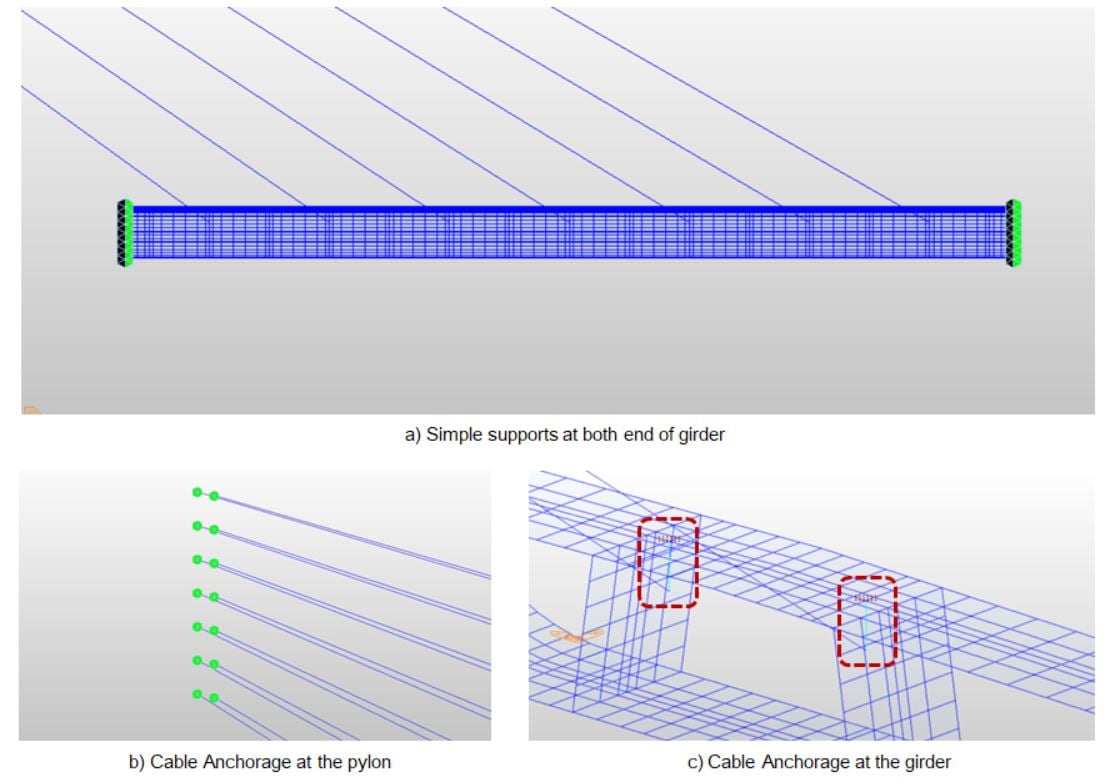
3. Boundary Conditions with Functions in midas Civil
- Define Supports function was used.
- Rigid Link function was used for the rigid zone of the girder section.
- It would be necessary to consider proper boundary conditions depending on model cases.
4. Post-processing and Other Modeling Applications
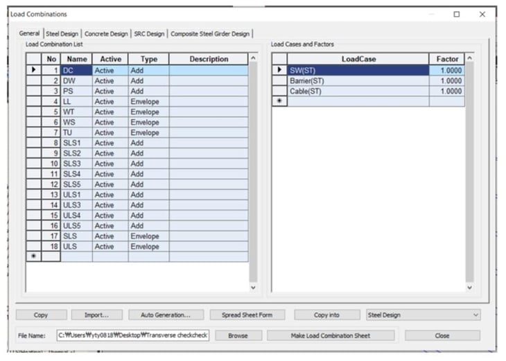
- Load Combination function was used to combine load cases.
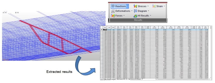
- Results function was used to get stresses & forces results.
- Results data can be used to optimize components in the structure. Checkpoints could be the section shape, reinforcements, tendons and etc.
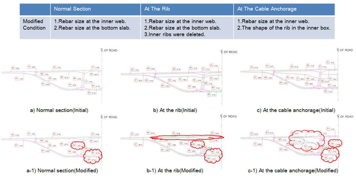
- In the detail design step, various ways can be used to get more detailed results.
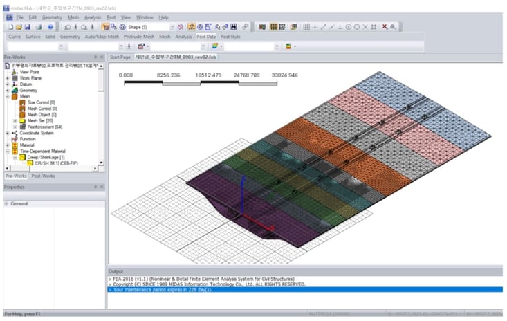
- There are other options for the detailed analysis in Midas SW family.
Conclusion
1. This application was carried out to check the capability of prestressed concrete box girders in the transverse direction under preliminary design.
2. The girder can be modeled as a frame, plate, and solid element.
In this case, plate elements were used.
3. For more detailed results and other design details, detailed analysis was carried out.
Watch the full webinar video