Please fill out the Download Section (Click here) below the Comment Section to download the Project Application
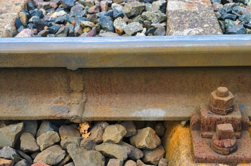
Most of the modern railways use continuous welded rail (CWR), sometimes referred as long weld rails (LWR). These rails are welded together by flash butt welding to form one continuous rail that may be several kilometres long. There are various benefits of using CWR over jointed tracks. As there are few joints:
-
This form of track is very strong
-
Provides a smooth ride
-
Needs less maintenance
-
Train can travel at higher speed with less friction
-
Reduced impact force on the rails
CWR are more expensive to lay as compared to jointed tracks but have much lower maintenance costs. Also, the reduction in impact force leads to increase in life span of CWR.
Why do we need Rail Structure Interaction (RSI) analysis?
CWR over a bridge structure typically experiences a large amount of additional longitudinal axial forces due to longitudinal rail-structure interaction (track bridge interaction) due to train vertical, braking/traction load effect and temperature change. Therefore, it is essential to ensure buckling stability by compressive stress and fracture by tensile stress due to the above mentioned loading effects.
RSI analysis focuses on the following key design actions:
RAIL
-
Forces attracted by the rail and the resulting additional axial rail stresses due to combined effect of temperature, vertical and braking/traction load.
-
Longitudinal relative displacement between deck and rail under these load effect to ensure the stability of the ballast in bridge.
BRIDGE
-
Forces and bending moment attracted by the substructure including pier column, pile cap and piles.
Guidelines for RSI analysis:
The International Union of Railways (UIC) is a worldwide professional association representing the railway sector and promoting rail transport. UIC has been a standards setting organization since its creation 1922, and technical harmonization of the railway system remains one of its core objectives. Its members - the operators of the world's railways - have, over the years, developed the "UIC code" comprising UIC leaflets, which define common rules to ensure safety and efficiency in the design, construction, operation and maintenance of the railway system.
UIC 774-3 provides a sound basis for RSI analysis of bridges. It provides design graphs for various spans, support condition and loading. Using these curves the interaction stresses in the rail can be found out. However there are limitations to the manual method of calculation of stresses. Manual approach is fine up to 2-3 spans, it cannot be applied to bridges with large number of spans as the process becomes tedious and the stresses obtained are also not accurate. For such structures computer assisted interaction analysis should be performed. UIC 774-3 also provides recommendations for computer assisted interaction analysis.
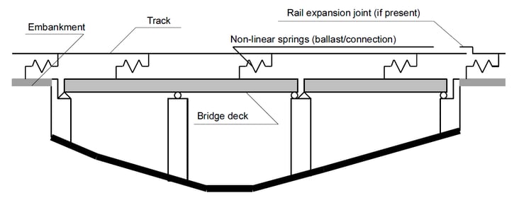 Fig. Structural diagram for the evaluation of track-bridge interaction effect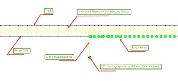
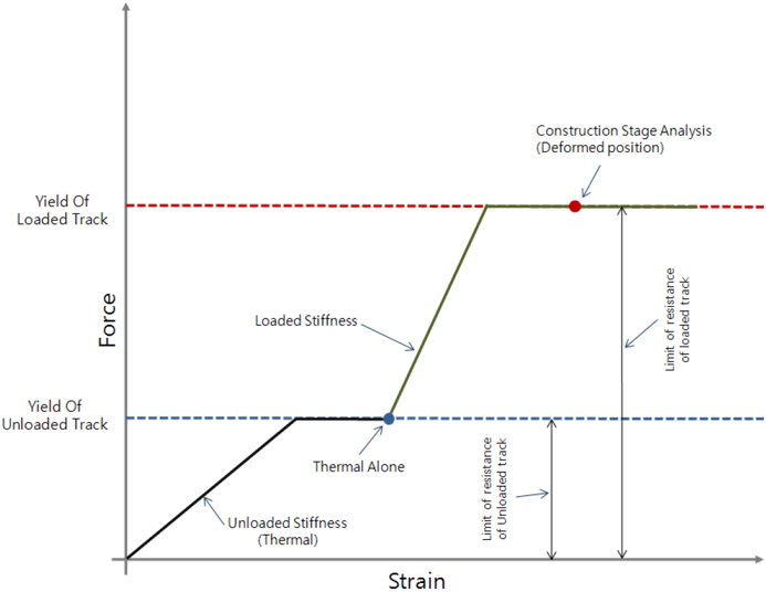
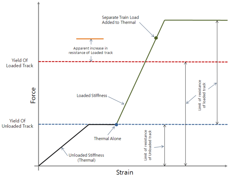
Depending on the importance and the structural scheme of the bridge. Different types of analyses can be made at different level of accuracy. Two major categories of analyses considered are:
1. Simplified separate analysis for thermal variations, braking/acceleration and vertical forces
2. Complete analysis of the joint effects of thermal variations, braking/acceleration and vertical forces
Comparison for theoretical and software output for RSI:
Below shown is a comparison of stresses and support reaction for a simply supported deck with one fixed elastic support between manual stresses calculated based the theoretical method given in UIC 774-3 and stresses obtained for the same bridge modeled in Midas Civil.
Bridge Data: Deck length, L= 75 m
Fixed support at one end, no friction in the movable bearing
Modulus of Elasticity: 2.10E+08 kN/m²
I: 2.59 m4, A: 0.74 m², H (Depth of section): 6.00 m, ω (location of centroid from top): 1.21 m,
γ = ω/H: 0.202, ΘH[LM 71] : 7.90 mm
Thermal Coefficient: 1.00E-05/ºC
Temperature variations for the rails, ΔTrails : +/-50ºC
Temperature variations for the deck, ΔTdeck: +/-35ºC
Load due to braking and acceleration: 20 kN/m
Calculation of stresses as per UIC 774-3: The stresses in rail are calculated based on the interaction diagrams due to braking and temperature variation for simply supported deck with single track given in Appendix A and Appendix B of UIC 774-3. The summary of stresses are shown below:
Temperature Stresses:
σrail (fixed) [ ΔT] = 11 N/mm²
σrail (movable) [ ΔT] = 34 N/mm²
Braking stresses:
σrail (fixed) [ Braking] = 32.5 N/mm²
σrail (movable) [ Braking] = 32.5 N/mm²
Vertical bending:
σrail (fixed) [ΘH] = 0
σrail (movable) [ ΘH] = 13 N/mm²
|
Total stress at fixed end : |
|
1.0 x σrail (fixed) [ ΔT] +1.0 x σrail (fixed) [ Braking] + 1.0 x σrail (fixed) [ΘH] |
|
11 + 32.5 + 0 = 43.5 N/mm²
|
|
Total stress at free end : |
|
1.0 x σrail (movable) [ ΔT]+1.0 x σrail (movable)[Braking]+1.0 x σrail (movable) [ΘH] |
|
34 + 32.5 + 13 = 79.5 N/mm²
Midas Civil Output:
|
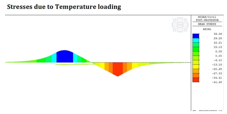
Fig. Stresses in rail due to temperature loading
Temperature stresses:
σrail (fixed) [ ΔT] = 36.36 N/mm²
σrail (movable) [ ΔT] = 41.48N/mm²
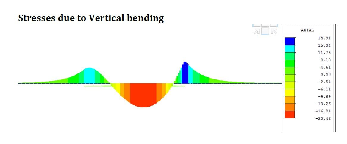
Fig. Stresses in rail due to vertical bending
|
Vertical Bending stresses |
|
|
σrail (fixed) [ ΔT] = 15.34 N/mm² |
|
|
σrail (movable) [ ΔT] = 18.91 N/mm²
|
|
|
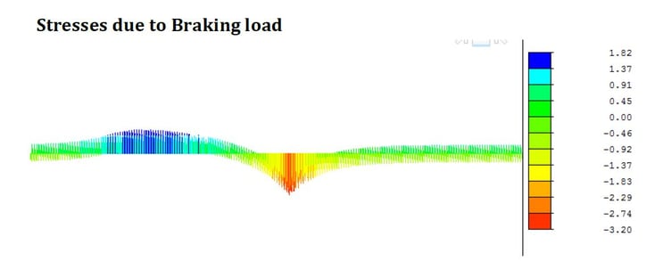
Braking Stresses: |
|
σrail (fixed) [ ΔT] = 1.82 N/mm² |
|
σrail (movable) [ ΔT] = 3.2N/mm² |
The comparison of stresses in rail for manual calculation and software results is shown below:
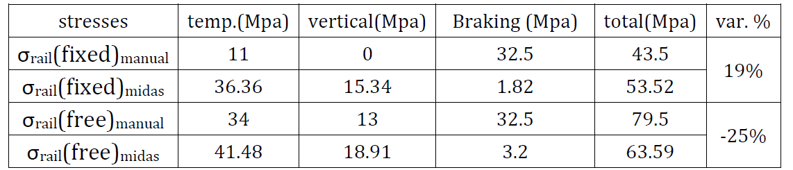
Conclusion:
It can be seen from the above comparison that the manual method mentioned in UIC 774-3 gives a conservative estimate of the stresses in rail due to interaction. Same is mentioned in UIC as well. However the point to notice here is due to continuity of rail which is accounted in Midas Civil the stiffness distribution of the structure changes resulting in change in stress distribution. This can be evidently seen in this example. Hence for larger bridges with multiple spans software based interaction analysis is a better option as it more accurately captures the stiffness of structure due to continuity of rail.