
A. Introduction
I started my design career at a small startup company. One of the advantages of the startup company is the limited number of staff, so I was able to learn the basic details of design from my team leader.
He didn't always give me the answers but asked me questions and pushed me to find the answers. One of those questions I still remember today is:
" Place the top reinforcement in the bottom slab of a box section."
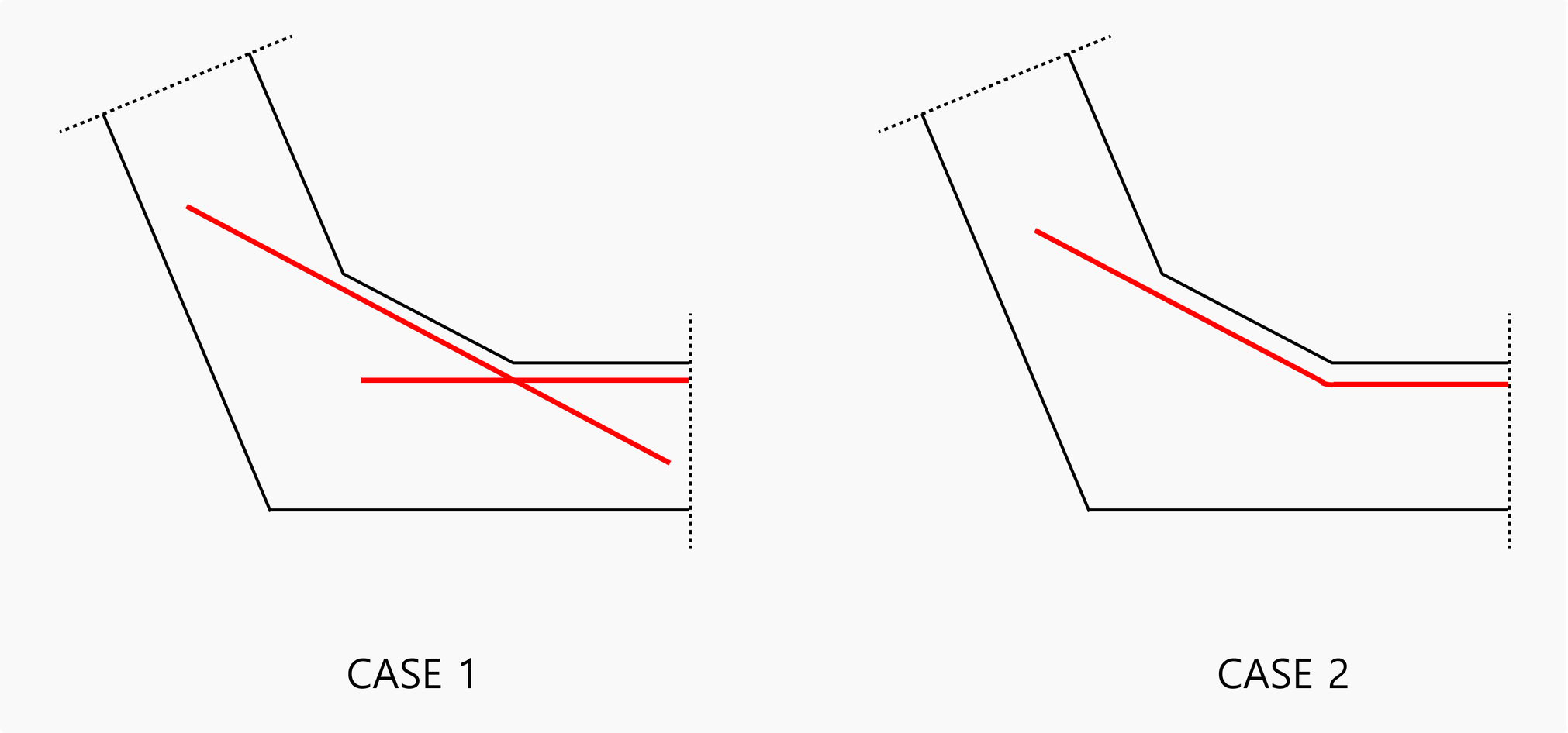
I immediately thought of CASE 1 and 2 and replied that it should be placed as CASE 1. After hearing my answer, the leader said, "Then explain why it can't be CASE 2."
I couldn't think of a reason why it shouldn't be CASE 2 right away, so I said I didn't know.
Then the leader gave me the following answer.
"Reinforcement is a member that is placed under tension, and imagine that the top reinforcement is under tension. In case 2, the bearing stress is generated inward where the reinforcement is bent. This would be incorrect placement because this stress could destroy the concrete cover."
Reinforcement placement is one of the most important factors that allow reinforced concrete structures to function properly.
Therefore, we need to understand and know exactly how the forces flow when placing the reinforcement so that we can design the structure appropriately.
In other words, an engineer needs to be able to place the rebar properly before they can determine the strength of reinforced concrete mathematically.
B. What is the development length?
When considering the placement of reinforcement, the "development length" is a critical part of the design.
In ACI, it is called "Development Length" and in Eurocode, it is called "Anchorage Length".
Let's take a look at the basic concepts of development length, and how they are calculated.
B.1 Development Length
The length of reinforcement that must be embedded in the concrete to prevent it from being separated from the concrete under force is called the development length.
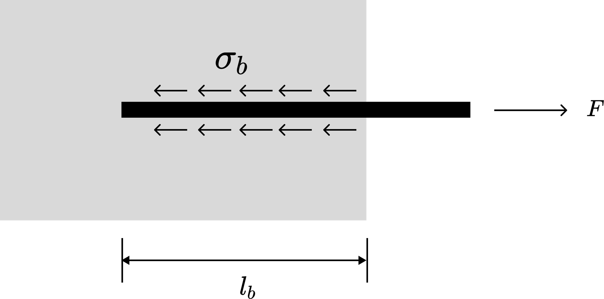 Figure 1. What is the development length?
To express this mathematically, the force F can be expressed as the cross-sectional area and stress of the reinforcement.

Where,
As = cross-sectional area of the reinforcement
σs = stress in the reinforcement
Φ = diameter of the reinforcement
The force resisted by the development length is called R, which is expressed as the area of the rebar and the bond strength of the concrete.

Where,
Asuf = perimeter area of the reinforcement
σb = concrete bond strength
Since F = R, the anchorage length, lb, can be expressed as

B.2 Bond strength
Let's understand the concept of bond strength.
In general, the anchorage of reinforcement is referred as to deformed steel. There are several types of forces that the deformed steel resists in the concrete, but the main one is the load acting on the RIB, which is expressed as follows.

This can be represented in terms of concrete as follows
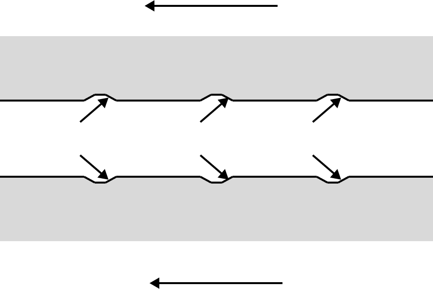
The force acting on each rib can be resolved into two forces, as shown in the figure below.
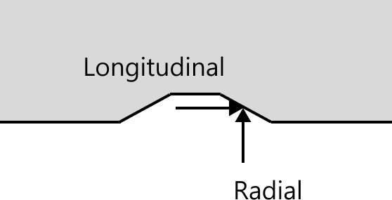
These forces dissipate radially around the perimeter of the reinforcement, causing cracks in the concrete.
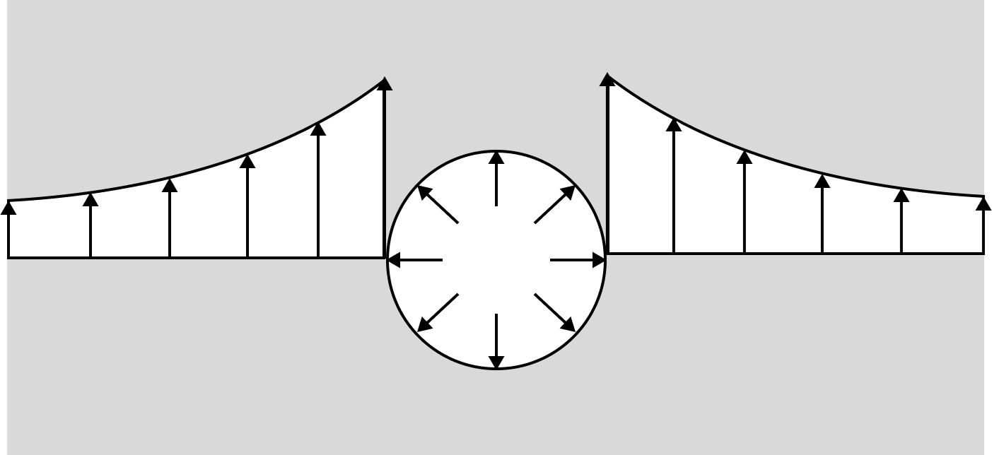
Figure 5. Crack formation in concrete
These forces in the form of radials show different crack shapes depending on the position of the reinforcement about the surrounding reinforcement subjected to the same force, as shown below.
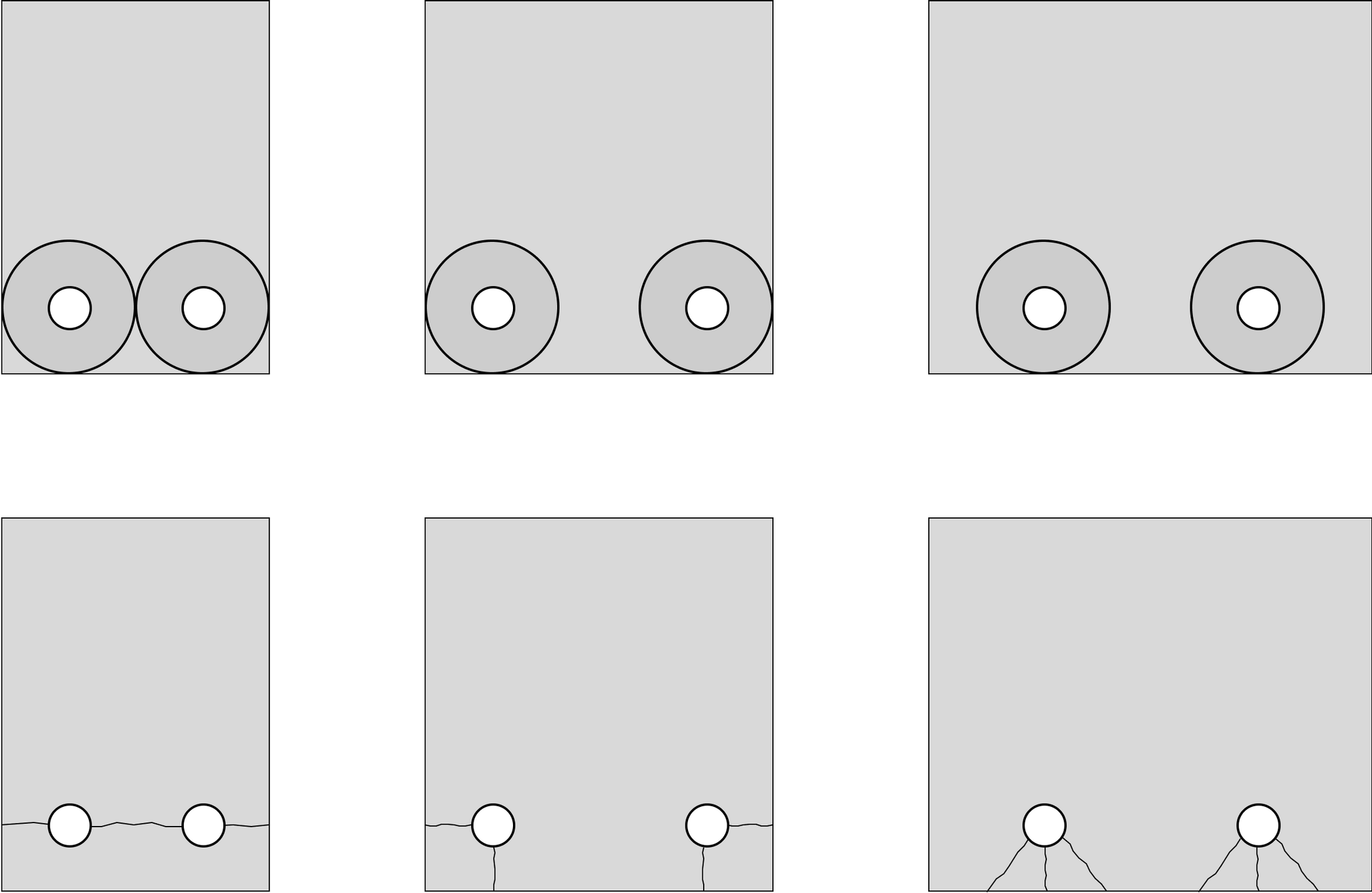
Therefore, it can be understood that the bond strength affects the tensile strength of the concrete, the spacing of the rebar, and the thickness of the cover.
C. Design Criteria
C.1 Development length consideration in design criteria
-
EN1992-1-1:2004 (KDS 24 14 00)
-
ACI 318M-19 (KDS 14 20 00)
C.1-1 Anchorage length of EN1992-1-1:2004
Clauses 8.4.2 through 8.4.4 of EN1991-1-1 indicate that the anchorage length is calculated using the following three equations.

If the above expression is combined into a single equation, it is expressed as follows.

Where,
a1,a2,a3,a4,a5 : Coefficients
φ: diameter of the reinforcement
σsd: Design stress of the reinforcement
fctd: Design tensile strength of the concrete
η1: Coefficient according to bonding condition
η2: Coefficient according to reinforcement diameter
C.1-2 Development length of ACI 318M-19
In ACI 318, the development length is based on the following equation.

Where,
ψt,ψe,ψs,ψg : Coefficients
db: Diameter of the reinforcement
CB: Distance between the center of the reinforcement and the concrete surface closest to it and half of the reinforcement center spacing, whichever is less.
Ktr : Contribution of confining reinforcement
fy: Design tensile strength of reinforcement
f’c : Design compressive strength of concrete

You can check more of these details in the download file.
C.2 Comparison
C.2-1 Location of reinforcement
C.2-2 Diameter of reinforcement bars
C.2-3 Reinforcement Surface
C.2-4 Grade of Reinforcing Steel
C.2-5 Types of reinforcement
C.2-6 Rebar spacing, cover thickness, and transverse reinforcement
C.2-7 Strength of Concrete and Reinforcement