Post-Tension Slab Analysis & Design
Please fill out the Download Section (Click here) below the Comment Section to download the Structural Design Guide for Prestressed Slabs.
Table of Contents
- Advantages & Applications of Post-Tensioning
- Post-Tension Type
- Strength of Prestressing Steel
- Design Steps
- Loading Conditions
- Definition of Member Forces
- Thickness or Depth of Section
- Post-Tension Slab Procedure
- Design Flow Chart for Post-Tension
What is Post-Tensioning?
Post-tensioning is a technique for reinforcing concrete. Post-tensioning tendons, which are prestressing steel cables inside plastic ducts or sleeves, are positioned in the forms before the concrete is placed. Afterward, once the concrete has gained strength but before the service loads are applied, the cables are pulled tight, or tensioned, and anchored against the outer edges of the concrete.
Post-tensioning is a form of prestressing. Prestressing simply means that the steel is stressed (pulled or tensioned) before the concrete has to support the service loads. Most precast, prestressed concrete is actually pre-tensioned-the steel is pulled before the concrete is poured. Post-tensioned concrete means that the concrete is poured and then the tension is applied-but it is still stressed before the loads are applied so it is still prestressed.
Advantages & Applications of Post-Tensioning
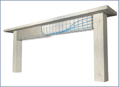
* Cracks that do form are held tightly together.
* It allows slabs and other structural members to be thinner.
* It allows us to build slabs on expansive or soft soils.
* It lets us design longer spans in elevated members, like floors or beam.
Post-Tension Type
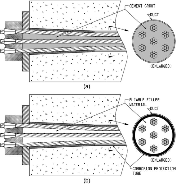
(a) Bonded Post-Tensioning
It is used for large structural elements such as beams and transfer girders, design advantages include increased span lengths and load carrying capacity and reduced deflection.
(b) Unbonded Post-Tensioning
It is typically used in new construction for elevated slabs, slabs-on-grade, beams, and transfer girders, joists, shear walls, and mat foundations. Light and flexible, the unbonded mono strand can be easily and rapidly installed – providing an economical solution.
Strength of Prestressing Steel
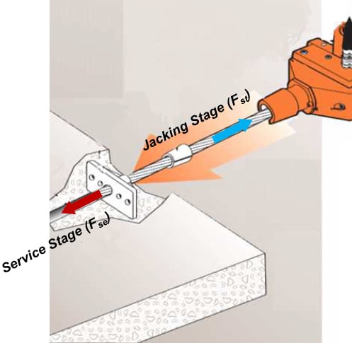
| Step | Immediately after prestressing | After anchoring |
| Tension Stress | Min[ 0.94 fpy, 0.80 fpu ] | 0.70 fpu |
| Diameter | Aps (mm2) | fpu (Mpa) | fpy (Mpa) | fpe (Mpa) | Fst (kN) | Fse (kN) |
|
12.7mm
|
98.71 | 1,860 | 1,674 | 1,200 | 146 | 118.4 |
| 15.2mm | 138.7 | 1,860 | 1,674 | 1,200 | 205 | 166.4 |
Aps : Area of prestressing steel
fps : Stress in prestressed reinforcement at nominal strength
fpu : Specified tensile strength of prestressing steel
fpy : Specified yielding strength of prestressing steel (0.90* fpu= 0.90*1,860Mpa = 1,674Mpa)
fpi : Initial prestress stress of prestressing steel
fpe : Effective prestress stress of prestressing steel (0.65* fpu= 0.65*1,860Mpa = 1,200Mpa)
Fst : Max. prestress force ( Min[ 0.94 fpy, 0.8 fpu ] *Aps = Min[ 1,573 or 1,485 ] *138.7 = 205kN )
Fse : Effective prestress force ( fpe*Aps = 1,200Mpa*138.7 = 166.4kN )
Fps : Ultimate prestress force
Design Steps
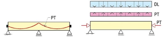
(a) Post-tensioned member (b) Tendon removed
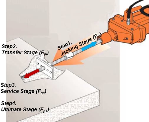
Step 1: Jacking Stage (Fst)
Step 2: Transfer Stage (Fpi)

(c) Service condition (SLS) (d) Strength condition (ULS)
Step 3: Service Stage (Fse) Step 4: Ultimate Stage (Fps)
After Jacking Stage
• Activity of anchorage device
• Tension force loss due to friction
• Tension loss due to elastic shrinkage of concrete
AfterTransfer Stage
• Tension loss due to creep
• Tension loss due to shrinkage
• Tension loss due to strand relaxation
Loading Conditions
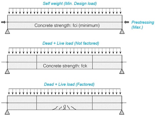
Transfer Stage
• Using Prestress Force → Fsi (before short/long-term tension loss occurs, Max. prestress)
• Using Concrete strength : fci (compressive strength of concrete when prestress is introduced, Min. strength)
• Loading : only Self-weight (before adding a finishing and live loads)
• Checking item : Tensile cracking and crushing of concrete, failure of anchorage part.
Service Stage
• Using Prestress Force → Fse (Effective tension after short/long-term tension loss occurs)
• Using Concrete strength : fck (Max. design strength)
• Loading : All design load (Unfactored Load)
• Checking item : Deflection, Crack Width.
Ultimate Stage
• Using Prestress Force → Nominal Strength
• Using Concrete strength : fck (Max. design strength)
• Loading : All design load (Factored loads)
• Checking item : Flexural failure or compression stress under flexural behavior.
Definition of Member Forces
Example 1: Continuous Beam
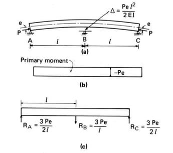
MS : Moment due to own weight of concrete section.
MO : Moment due to other applied loads.
M1 : Primary moment → Moment by the distance between the section center and the prestressing point.
In example 1: M = Prestressing force x Eccentricity distance = P x -e = -Pe
Δ : Deflection by M1 →Deflection at point B when considered as a simple beam.
In example 1 : "Δ"=(Mol2 )∕8EI= (Pe(2l)2 )∕8EI=(Pel2 )∕2EI
R : Reaction by Δ → Point B should not be deflected by the support, so a reaction force is generated so that deformation as much as (-)Δ occurs.
In example 1 :
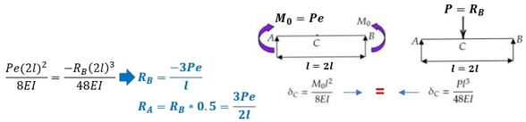
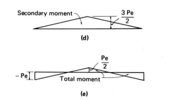
MSecondary : Secondary Moment → Moment caused by R
* MSecondary means the moment created by the reaction force that restrains the deformation caused by M1.
In example 1 : 𝑀𝑆𝑒𝑐𝑜𝑛𝑑𝑎𝑟𝑦 𝑎𝑡 𝑝𝑜𝑖𝑛𝑡 𝐵=(3𝑃𝑒/2𝑙)×𝑙=3𝑃𝑒/2
MNet : Net final Moment = M1 + MSecondary : Moment acting on the actual continuous beam by prestressing.
In example 1 : 𝑀u 𝑎𝑡 𝑝𝑜𝑖𝑛𝑡 𝐵=−𝑃𝑒+(3𝑃𝑒/2)=𝑃𝑒/2
Thickness or Depth of Section
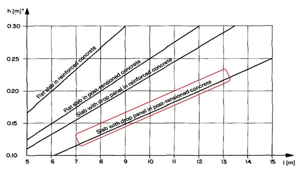
<Thickness-span correlation by each slab system>
• RC Member
| Span/Depth | Continuous span | Simple span |
| Beam | 21 | 16 |
| 2-way slab | 30 | - |
| 1-way slab | 28 | 20 |
• Post Tension Member
| Span/Depth | Continuous span | Simple span | ||
| Roof | Not Roof | Roof | Not Roof | |
| Beam | 60% | 70% | 53% | 62% |
| 2-way slab | 63% | 71% | - | - |
| 1-way slab | 56% | 62% | 44% | 50% |
• Reduction ratio of thickness or depth when PT is applied
| RC/PT (%) | Continuous Span | Simple span | ||
| Roof | Not Roof | Roof | Not Roof | |
| Beam | 60% | 70% | 53% | 62% |
| 2-way slab | 63% | 71% | - | - |
| 1-way slab | 56% | 62% | 44% | 50% |
The thickness is reduced by 30-50% compared to the RC member. Alternatively, an economical design can be made by reducing the amount of rebar or tendon required for the same thickness.
Post-Tension Slab Procedure
Step 01 : Installing slab formwork
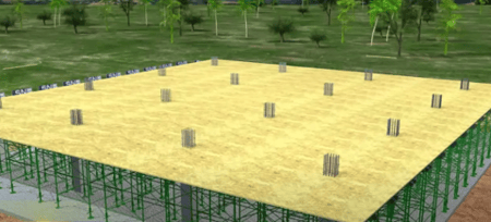
Step 02 : Installing slab rebar
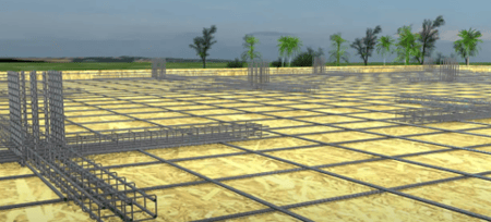
Step 03 : Placing bar chair by profile height
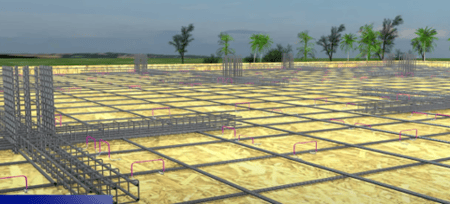
Step 04 : Placing tendon on the bar chair
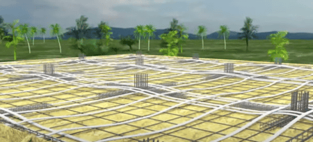
Step 05 : Add extra rebar
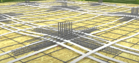
Step 06 : Pouring concrete
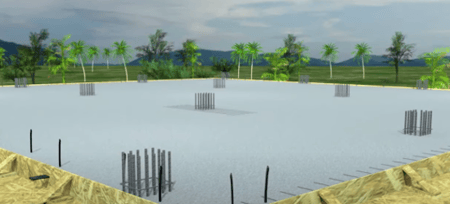
Step 07 : Insert block and jaws bar chair
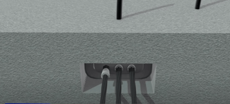
Step 08 : Stressing and measuring elongation
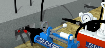
Step 09 : Grouting
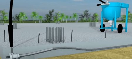
Design Flow Chart for Post-Tension
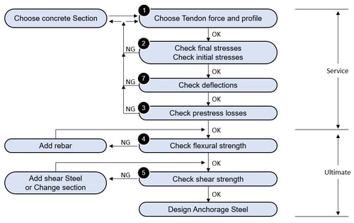
1. Choose Tendon force and profile
Tendon Profile Type
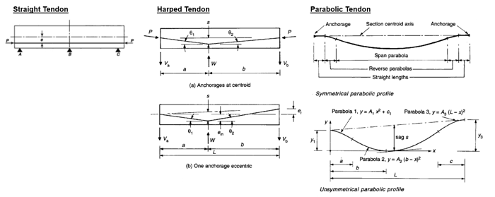
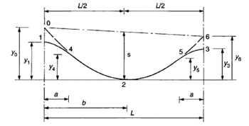
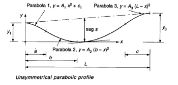
How to arrange tendon of parabolic shape
After Transfer Stage
2. Check final stresses and Check initial stresses
Allowable stress for Concrete unit : (MPa)
| Checking Stage | Conditions | Allowable stress |
| under Initial Service Load (Initial) | 1. Extreme fiber stress in compression | pci = 0.60 fci |
| 2. Extreme fiber stress in tension | pti = 0.25 fci0.5 | |
| 3. Extreme fiber stress in tension at ends of simply supported members | pti = 0.50 fci0.5 | |
| under Service Load (Final) | 1. Extreme fiber stress in compression (at Long-Term Service Load) | pcf = 0.45 fck |
| 2. Extreme fiber stress in compression (prestress + total load) | pcf = 0.60 fck | |
| 3. Extreme fiber stress in tension | ptf = 0.50 fck0.5 |
Allowable stress for Tendon (Strand) unit : (MPa)
| Checking Stage | Conditions | Allowable stress |
| During Stressing | - | Max [0.94 fpy, 0.8fpu] |
| Immediately after stressing | - | 0.70fpu |
Please download the white paper of Structural Design Guide for Prestressed Slabs below to see the full contents.