Please fill out the Download Section (Click here) below the Comment Section to learn more about CIM
Modeling of Steel Box Bridge Using CIM
*Click the content to move to the section
�� Click Here to Learn More about Steel Bridges
1. Introduction
Many people ask, "Are there any useful materials or tutorials available for modeling steel bridges?"
Until recently, the models of bridges using midas CIM mainly focused on concrete bridges.
Through this article, we'd like to provide a brief introduction to the modeling of Steel Box Bridges using CIM.
2. Description
1) The specifications of the Steel Box Bridge are as follows:
- Superstructure type: Steel Box Girder
- Span configuration: L=55.0m (single span) / Width: 12.0m / Skew angle: 90 degrees
- Plan alignment: Straight / Longitudinal slope: 2% / Superelevation: -2% on both sides
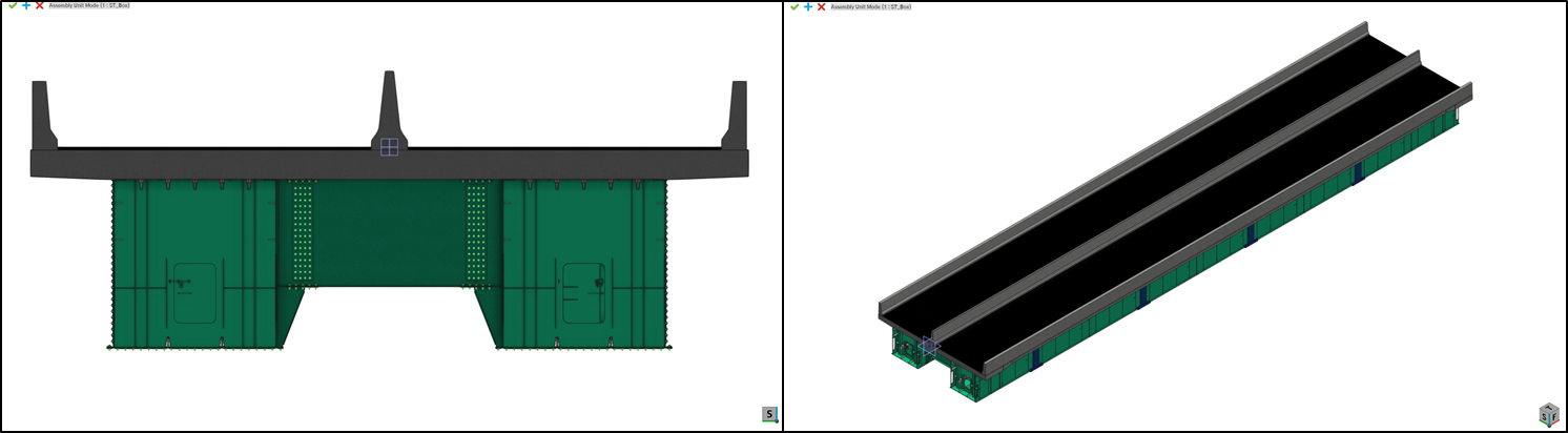
2) Method of Model Creation (Library)
- Utilizing User Sections, the upper/lower flanges and web are combined into a single section to create the Steel Box model.
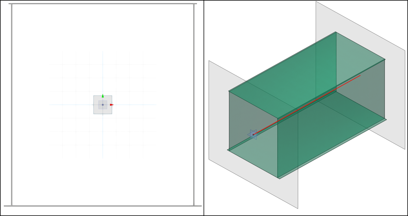
In the model created this way, Stiffeners, Bolts, and Studs are generated using the Stiffener Draw Mode.
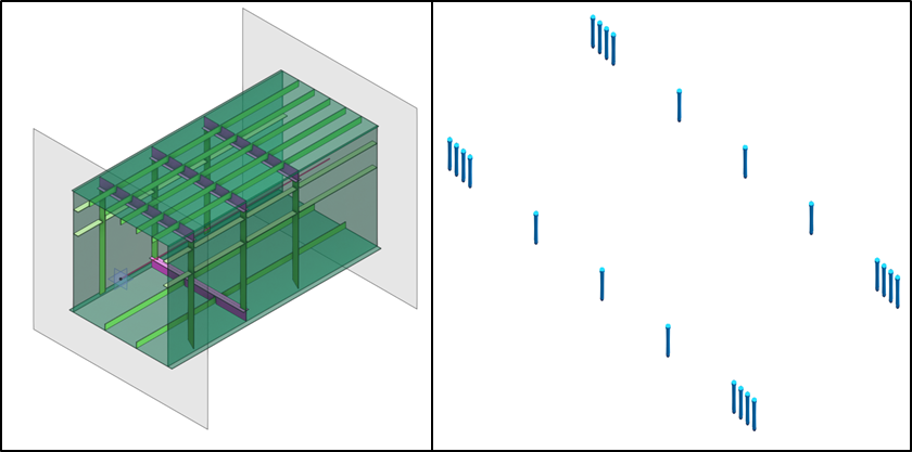
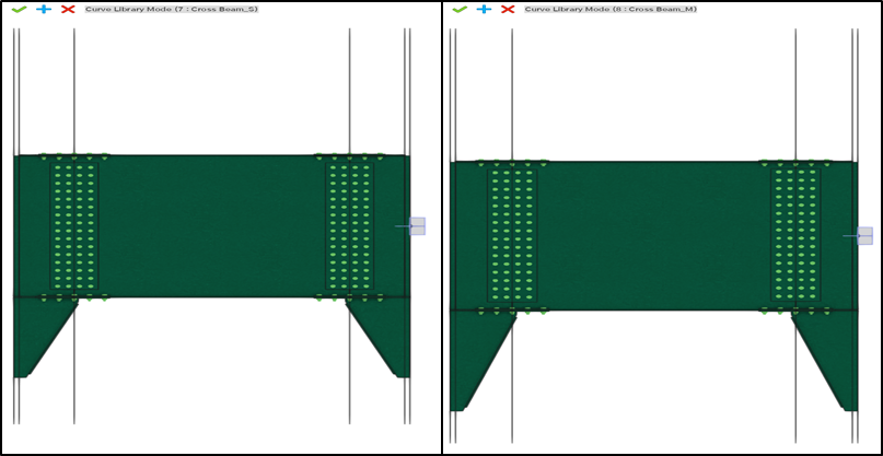
- Cross Beam: This is a library generated to match the crown slope (left and right -2%) (at junction and center).
- Note: If different values for left and right superelevations are applied, additional modeling needs to be done as per the situation.
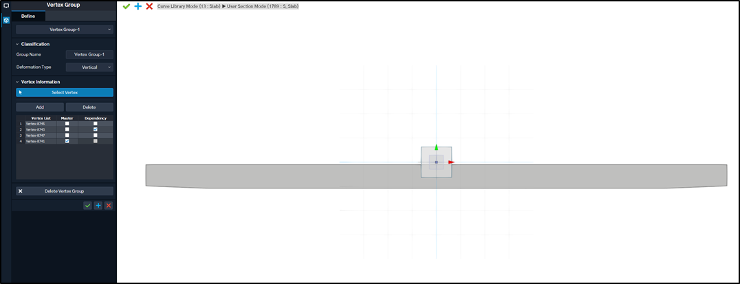
- Upper Slab: The modeling for the upper slab is created using User Section and Vertex Group to accommodate the superelevation accordingly.
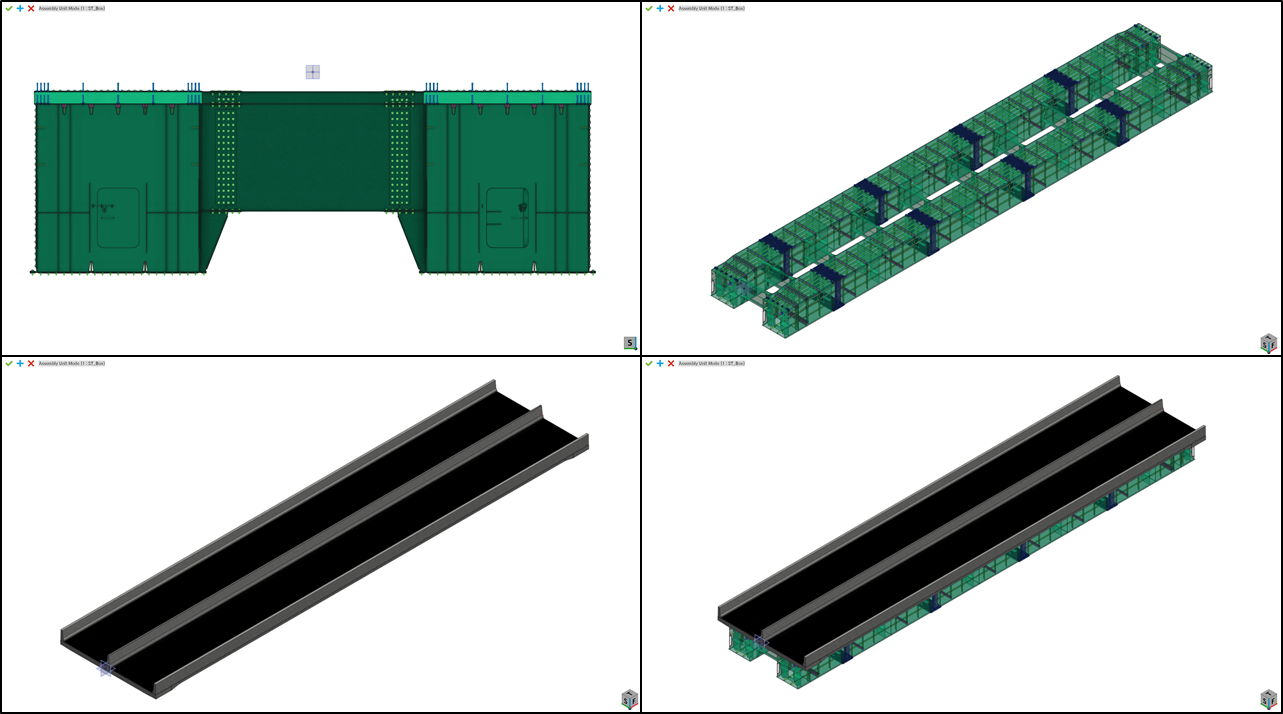
3) Assembly Unit Creation
- The generated libraries are combined to create an assembly unit.
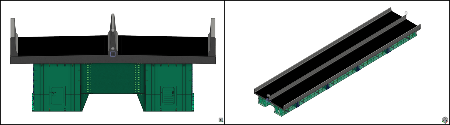
4) Generation and Allocation of Linear Information
- Planar Alignment: Straight
- Longitudinal slope: 2%
- Superelevation: Left -2%, Right -2%
3. Conclusion
Starting with the modeling of the Steel Box Bridge, we will continue to present various practical cases to demonstrate that "Steel bridges are also CIM."
Midas will take the lead in this rapidly changing era to continuously update convenience features and functionalities for CIM completion. We kindly ask for the users' continued interest and support. 😊
Please fill out the Download Section (Click here) below the Comment Section to learn more about CIM