Loading on structures can be idealized as static loads and are one of the major issues for structures. It makes permanent deformations to structures during the service period. The dead loads can be applied in the structural analysis as static loads. The static loads include nodal loads, distributed loads, and pressure loads in the structural analysis software. midas Civil also provides various load types to cover various loading conditions. In this webinar, we will examine how static load types are applied and which static load types are available.
The webinar contains short training for applying the Static Loads function in midas Civil. Furthermore, it introduces some application models to check how the Static Loads function is used. We recommend this webinar to beginners of midas Civil or engineers who are not familiar with FEM software.
This tutorial highlights:
1. Basic training for using static loadings
We will see load types in the Static Loads function of midas Civil, and also, take a look at demonstrations about frequently used types in Static Loads function.
2. Application models under static loading
We will see application models including static load types. While we take a look at example models, we will check how static load types are used to loading conditions.
3. Tips and advanced features
Static load types can be applied quickly. midas Civil has several options to speed up the user's tasks. This webinar will show some useful options. Moreover, we will have a look at additional options for advanced analysis.
What are dead loads?
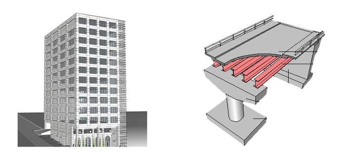
Dead loads are one of the design loads in several design codes for structures and make permanent deformations to structures during the structures' service period. The weight of structures or attachments is a common case of a dead load. For instance, in a building, the weight roofs, walls, floors, columns, attachments, etc, can be considered dead loads. In bridges, the weight of girders, slabs or decks, piers, abutments, pavements, and other attachments can be considered as dead loads.
How to apply dead loads to an analysis model?
Analysis SW provides various load types that cover various loading conditions. midas Civil provides static loads function groups under the Load tab, including Self-weight, Nodal Loads, Beam Loads, and Pressure Loads function.
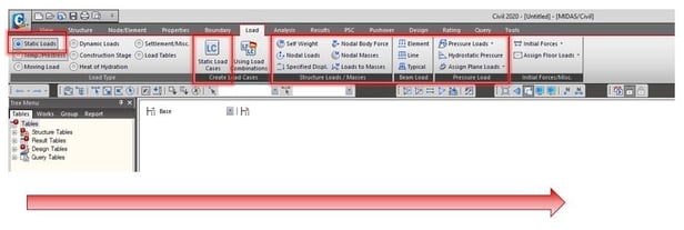
In order to define a load case, follow this procedure:
1. Click the Load tab.
2. Select Static Loads under the Load Type.
3. Click Static Load Cases and create a static load case.
4. Select a load type desired among the nodal nodes, beam loads, pressure loads.
5. Input values for loading and connect a load case.
Details of Each Function
1. Static Load Cases function
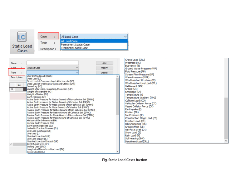
Before we use each load function, we should define a load case via the Static Load Cases function. While running the analysis, the software will perform static analysis for each load case. When we define a load case, we should select a load type. There are many load types prepared in the function, but those are used when the autoload combinations functions which Auto Generation of Load Combinations in Load Combinations function is used. Therefore, if the user does not use the autoload combination feature, it is optional to select a load type. The user can select the User-Defined Load type or another function available.
2. Self-Weight function
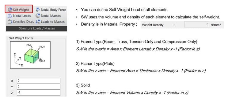
Through this function, we can consider the weight of a structure easily. The self-weight is calculated with the volume of a structure, the weight density defined in material property, and the scale factor defined in this function. If the shape of a structure is not complex, we can compare analysis results and hand calculations.
3. Nodal Loads function
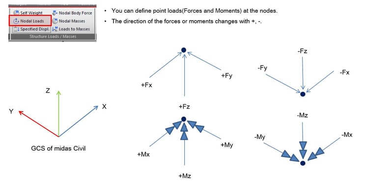
This function applies point loads to nodes of elements where available load types are axial forces and moments. The direction of loads follows the global coordinates system.
4. Beam Loads function
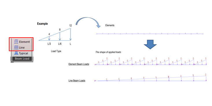
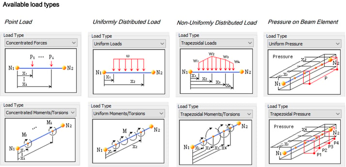
The Beam Loads function is subdivided into the Element Beam Loads function and the Line Beam Loads function. These functions apply point loads or distributed loads to beam elements. The Element Beam Loads function applies a load to each beam element. However, the Line Beam Loads function considers several beam elements as one element when loads are applied, as shown in the figure below.
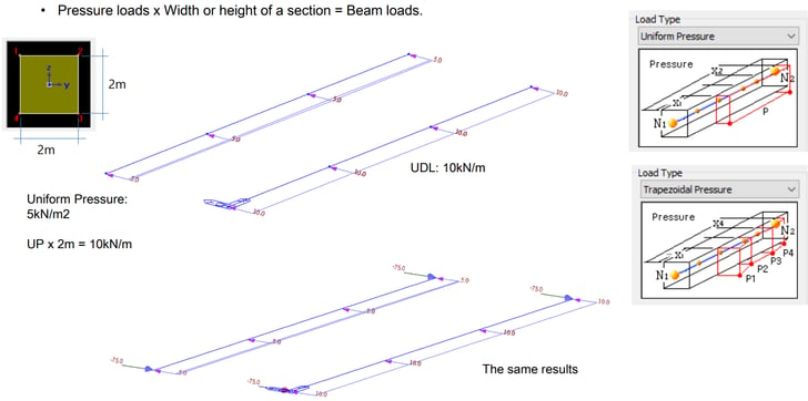
Mainly, pressure loads can be applied through the Pressure Type function. Applied pressure loads are re-calculated as a uniformly distributed load considering the width or height of sections. Therefore, if pressure loads are provided as a design load and the users have beam elements as a model, users can use this function without additional calculation for input.
5. Pressure Loads function
This load type can be applied to plate elements and surfaces of solid elements. There are two ways to apply the pressure load:
1. Applying Pressure Loads with Define Pressure Load Type
The first way is to use the Define Pressure Load Type option. Here, we can define up to 8 load cases and apply all load cases to elements at once.
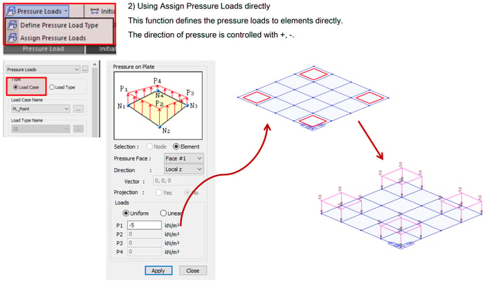
2. Applying Pressure Load without Define Pressure Load Type
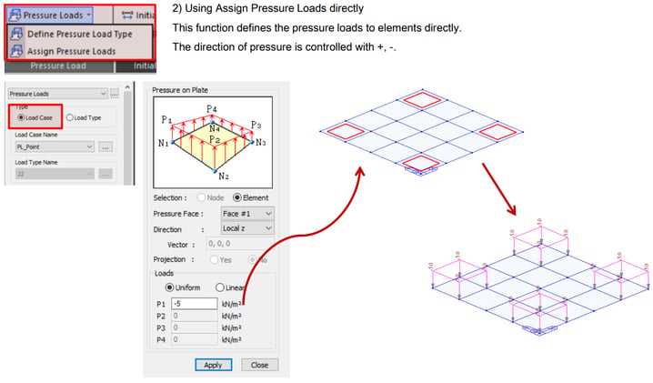
The second way is to apply the pressure loads to elements directly. We select a type of pressure load and apply it to the elements selected.
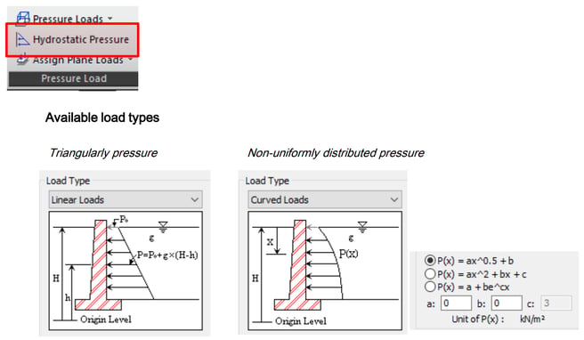
6. Hydrostatic Pressure Loads function
Through the Hydrostatic Pressure Loads function, users can apply a Triangular shape or non-uniformly shape of pressure easier than the pressure loads function. This function can be used to consider the soil pressure or water pressure.
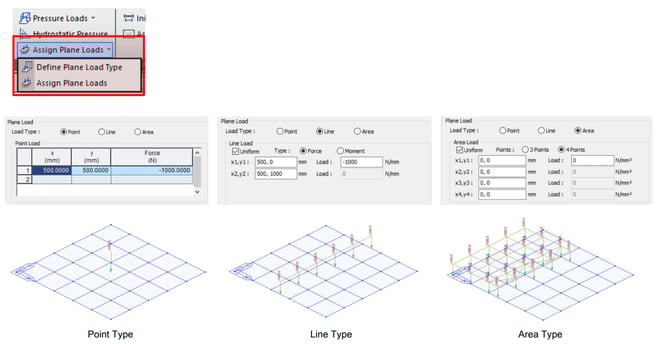
7. Plane Loads function
This function applies a load type defined in advance to the assigned plane. If there are elements in the assigned plane, the load will be placed on the elements. The important this is that the plane load type can be applied regardless of the mesh plan of elements.
Application Models under Static Loading
Now, let us see how the Static Loads group functions are applied to models in midas Civil.
1. Application models with Self-Weight function
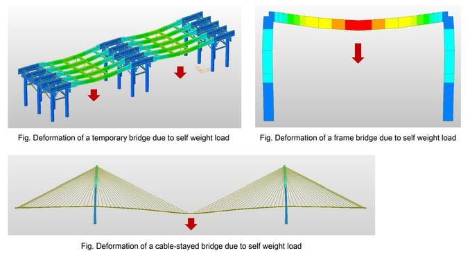
Self-weight loads can be used in various structure models. The major reactions of structures against self-weight load show the deformation toward gravity, as shown in the figures.
2. Application models with Nodal Loads function
Nodal loads can be used to consider the weight of devices for construction. The devices could be a derrick crane, a lift crane, and a form traveler. For instance, in the figure below, the weight of form travelers and the eccentric loading of form travelers are considered nodal loads.
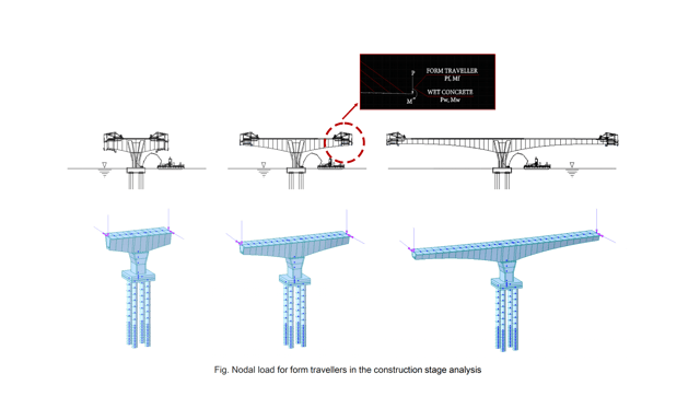
Here, Nodal Loads are applied in the transverse analysis for a concrete box girder model.
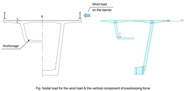
The Nodal Loads function is used to consider the vertical component of prestressing force and wind load on the barrier.
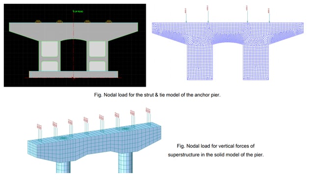
These example models are plate and solid models for a pier. Nodal loads are considered to apply the weight of the superstructure to the top of a pier.
3. Application models with Beam/Line Element Loads function
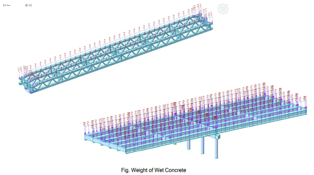
In this example, beam loads are applied to grillage models for girder bridges. During construction stage analysis, beam loads are used to consider the weight of wet concrete for the slab on girders.
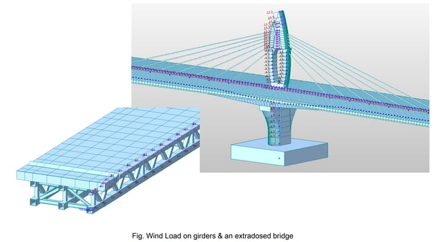
Here, beam loads are used to consider wind loads on bridges.
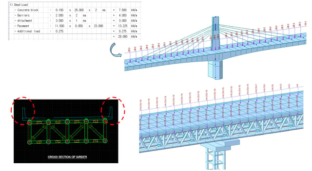
In these applications, beam loads are used to consider additional dead loads such as barriers, pavement, and other attachments. Additional dead loads can be applied individually to their location of a model or applied as total value.
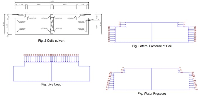
The next model is a culvert with beam loads. The culvert is modeled with beam elements. Therefore, beam loads are applied to consider external loading. The external loadings such as soil pressure, water pressure, and live loads are applied using the beam loads function.
4. Application models with Pressure/Hydrostatic Pressure/Plane Loads function
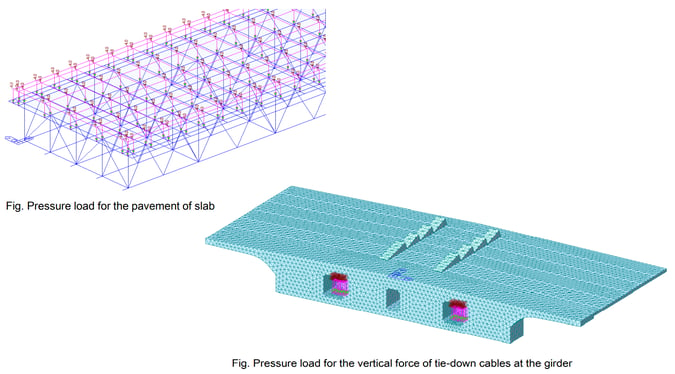
The last application models are examples of applying the Pressure, Hydrostatic pressure, and plane loads function. These example models consist of plate elements and solid elements. Pressure loads are used to consider the weight of pavement, barriers, and additional attachments.
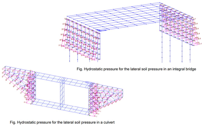
These models are an integral bridge and a culvert that contains plate elements. Here, the Hydrostatic pressure loads function is used to consider soil pressure and water pressure.
The last model applies Plane loads function. This girder model has plate elements. When meshing this model, it does not consider loading location. Therefore, the plane loads function is used because plane loads can be applied regardless of node location.
%20in%20a%20girder%20with%20plate%20elements.png?width=640&name=Plane%20load%20(Area%20type)%20in%20a%20girder%20with%20plate%20elements.png)
Watch the full webinar video