Pushover Hinge Definition in midas Civil
Table of Contents
1. Introduction
2. Pushover Hinge Properties
3. Example of GSD Import Type Hinge
4. Summary
1. Introduction
Pushover Analysis is a non-linear static analysis procedure to estimate the capacity of a structure beyond its elastic limit to understand the post-elastic behavior. Majorly, it allows us to evaluate overall structural behaviors and performance characteristics and enables us to investigate the sequential formation of plastic hinges in the individual structural elements constituting the entire structure. Displacement demand can be determined from Response Spectrum Analysis and displacement capacity can be determined from Pushover Analysis.
In the pushover analysis, the hinges are predicted at the potential weak areas and the sequence of damage at these hinge locations is tracked till the collapse of the structure. Hinge represents a localized force-displacement relation of a member through its elastic and inelastic phases under lateral loads. Figure 1 explains the brief procedure for pushover analysis.
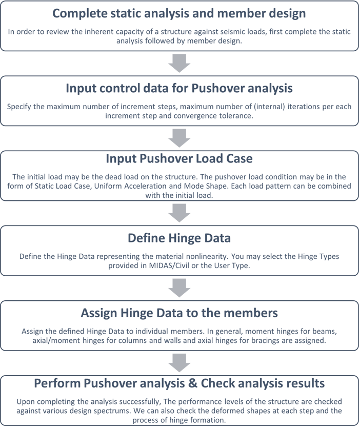 Figure 1: Procedure for Pushover Analysis
2. Pushover Hinge Properties
In midas Civil, pushover hinge properties can be added using the dialog box shown in Figure 2.
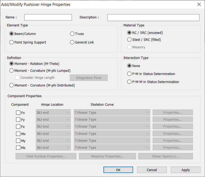
Five main components of pushover hinge properties are listed below:
1. Element Type
2. Material Type
3. Definition
4. Interaction Type
5. Component Properties
2.1 Element Type
Beam/Column : Hinge to be assigned to Beam or Column element
Truss : Hinge to be assigned to Truss element
Point Spring Support : Hinge in the form of point spring support
General Link : Hinge in the form of general link
2.2 Material Type
Specify the type of material used for the corresponding element.
RC / SRC (encased) : RC or SRC (Concrete encased steel type)
Steel / SRC (filled) : Steel or SRC (Concrete filled steel tube type)
2.3 Definition
Specify the load-deformation relationship of the flexural member in terms of Moment-Rotation (M-θ) or Moment-Curvature (M-φ Lumped) or Moment-Curvature (M-φ Distributed) can be specified.
When Moment-Curvature (M-φ Lumped) is selected, then we can specify the pushover hinge length and also specify the integration point of the hinge length whether it is End or Center. For example, if L is the length of an element which is not necessarily the entire column. If the entire column is modeled as one element, you can define hinge lengths at both the I-end and J-end of the element to represent hinge lengths of both ends of the entire column. If the column consists of two elements, you need to define hinge lengths at the I-end of one element and at the J-end of the other element.
2.4 Interaction Type
Specify the interaction type that will be used for the hinge.
None: Axial force and biaxial moments are uncoupled from each other.
P-M in Status Determination: Coupled axial force-Uniaxial moment behavior is reflected by calculating the flexural yield strength of a hinge considering the effect of axial force. It is only applicable for beam/column element types.
P-M-M in Status Determination: Coupled axial force-biaxial moment behavior is reflected by calculating the flexural yield strength of a hinge considering the effect of axial force. It is only applicable for beam/column element types.
2.5 Component Properties
For Pushover hinge, we can specify the hinge property in six degrees of freedom(Fx, Fy, Fz, Mx, My, Mz), and the corresponding skeleton curve can be given.
2.5.1 When Moment-Rotation (M-Theta) is selected, the skeleton curves available are as follows:
- Bilinear Type
- Trilinear Type
- FEMA Type
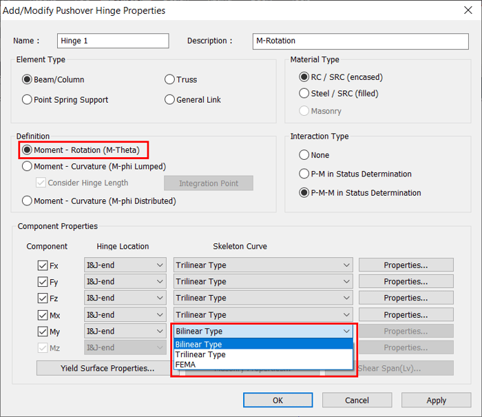 Figure 3. Moment-Rotation (M-Theta) - Skeleton curves
|
Component |
Definition of hinge properties |
Initial stiffness |
Location of hinge |
|
Fx (Axial) |
Axial force - Strain (Relative Displ.) |
EA/L |
Middle |
|
Fy, Fz (Shear) |
Shear force- Shear strain |
GAs/L |
Middle |
|
Mx (Torsion) |
Torsional moment - Rotation |
GJ/L |
I-end, J-end |
|
My, Mz (Flexure) |
Flexural moment - Rotation |
6EI/L,3EI/L,2EI/L |
I-end, J-end |
Table 1 illustrates the definition of hinge properties for various components and the initial stiffness used when moment-rotation (M-Theta) is selected.
2.5.1 When Moment-Rotation (M-Theta) is selected, the skeleton curves available are as follows:
- Bilinear Type
- Trilinear Type
- GSD Import Type
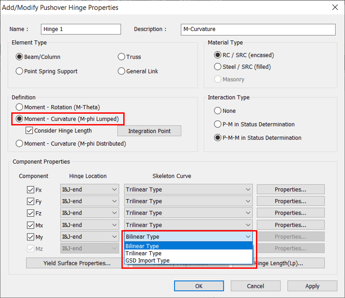 Figure 4. Moment-Curvature (M-phi Lumped) - Skeleton curves
|
Component |
Definition of hinge properties |
Initial stiffness |
Location of hinge |
|
Fx (Axial) |
Axial force - Strain |
EA |
Integration point |
|
Fy, Fz (Shear) |
Shear force- Shear strain |
GAs |
Integration point |
|
Mx (Torsion) |
Torsional moment - Curvature |
GJ |
Integration point |
|
My, Mz (Flexure) |
Flexural moment - Curvature |
EI |
Integration point |
Table 2 illustrates the definition of hinge properties for various components and the initial stiffness used when moment-curvature (M-Phi Lumed) is selected.
2.5.3 When Moment-Curvature (M-φ Distributed) is selected, the skeleton curves available are as follows:
- Bilinear Type
- Trilinear Type
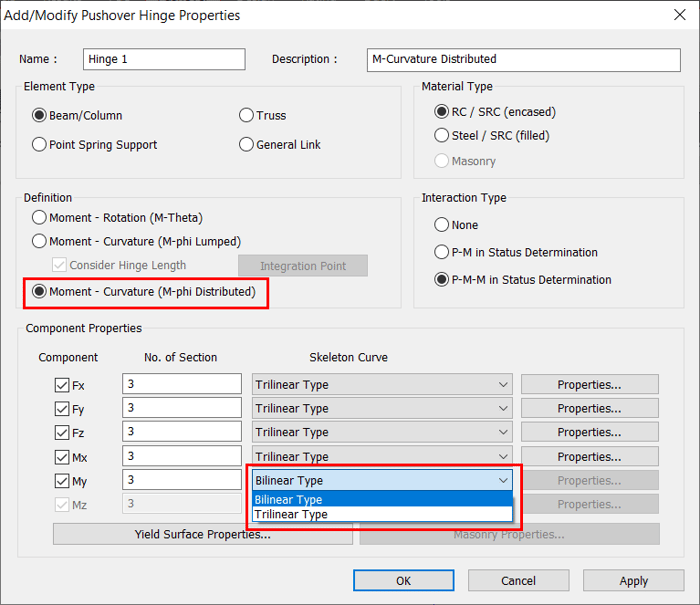 Figure 5. Moment-Curvature (M-phi Distributed) - Skeleton curves
|
Component |
Definition of hinge properties |
Initial stiffness |
Location of hinge |
|
Fx (Axial) |
Axial force - Strain |
EA |
Integration point |
|
Fy, Fz (Shear) |
Shear force- Shear strain |
GAs |
Integration point |
|
Mx (Torsion) |
Torsional moment - Curvature |
GJ |
Integration point |
|
My, Mz (Flexure) |
Flexural moment - Curvature |
EI |
Integration point |
Table 3 illustrates the definition of hinge properties for various components and the initial stiffness used when moment-curvature (M-Phi Distributed) is selected.
The direction properties of the pushover hinge are automatically calculated using the section and reinforcement information already provided in the program, if the Input Method is set to Auto-Calculation (Or) the user may enter the values of Yield Moment manually if Input Method is set to User-Input. The coordinate system follows the Element local Coordinate System.
3. Example of GSD Import Type Hinge
When Moment-Curvature (M-phi Distributed) and P-M/P-M M in the status determination are selected, then “GSD Import Type” skeleton curve can be defined for My component and will be identical to that of Mz component.
The confinement of concrete by suitable arrangement of transverse reinforcement in the form of spirals or circular hoops or of rectangular arrangement of steel results in a significant increase in both the strength and ductility of concrete columns. The concrete model confined by transverse rebar, which was suggested by Mander (1988) can be defined in Midas GSD as shown in figure 6.
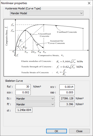 Figure 6. Mander model
Detailed confinement properties can be defined as shown in figure 7.
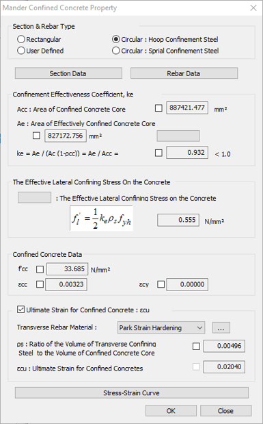
Once the material data (unconfined and confined concrete properties), sectional information, reinforcement data are specified in Midas GSD module, then we can obtain the moment-curvature data as shown in figure 8. Please note that Options> Design Code > “Eurocode2:04” needs to be selected for GSD Import type hinge though the moment-curvature data is not affected by the design code selected.
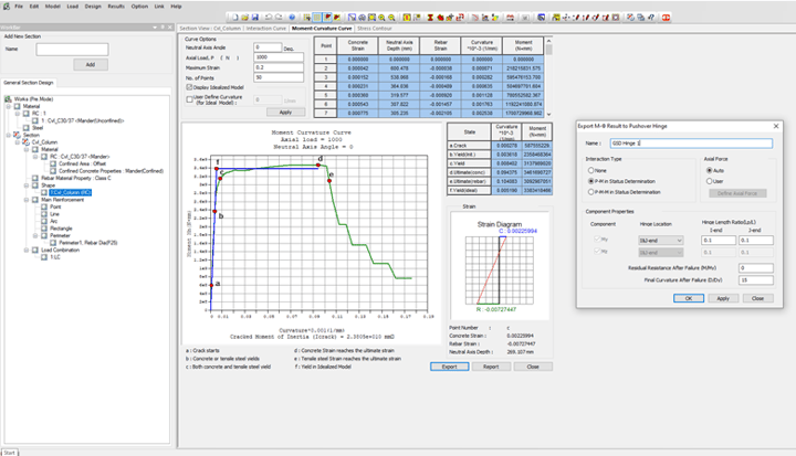 Figure 8. Midas GSD - Moment-Curvature curve
Once we link Midas GSD to Midas Civil, we can click on “Export” and then the Hinge is automatically exported to Midas Civil with the relevant Yield surface properties as shown in figure 9. The yield surface of the two axes can be checked by the table. The Interpolation Method: My-Mz is used to develop the full Yield surface, as figure 10 explains the interpolation types.
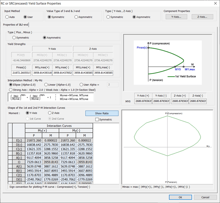 Figure 9. GSD import type hinge - Yield surface properties
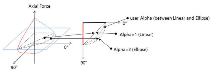 Figure 10. Interpolation methods
Directional properties of the hinge like Axial Load vs Yield Moment My, Axial Load vs Yield Moment Mz are generated automatically as shown in figure 11. The yield curvature (DY) is not considered directly from Midas GSD, instead, it will be recalculated for each axial load by using the formula Myo/EI. (Myo is taken directly from Midas GSD). So, It is important to note here that we have a choice of entering 1) EI value or 2) Yield Curvature (DY0). Moreover, we can see that this DY0 user input remains the same for all axial loads as only one value of EI is calculated and taken into Hinge calculations.
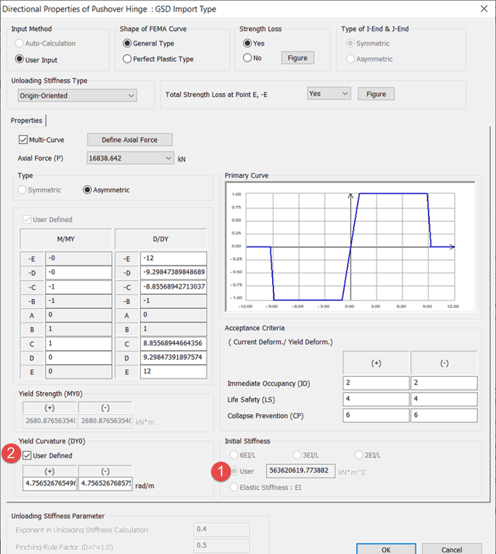 Figure 11. GSD Import Type Hinge - Directional properties
Once, the hinge properties are reviewed, we can assign the GSD Type Hinge to the pre-determined/predicted location of the plastic hinge and then run pushover analysis and check the plastic hinge formation.
4. Summary
Pushover hinges are assigned in structural models at the regions where one expects cracking and yielding to occur in relatively higher intensity under lateral/cyclic loading. So it is important to understand which type of hinge needs to be selected and then define the appropriate hinge properties to capture the plastic behavior at that region.