Introduction
Reinforced earth walls rely on the interaction between soil, facing, and reinforcement. A reliable stability assessment should therefore evaluate not only whether the wall is stable, but also how deformation develops and where failure is likely to occur.
The Limit Equilibrium Method (LEM) is widely used to calculate a global factor of safety by identifying a critical slip surface. The Finite Element Method (FEM), meanwhile, provides additional insight into stress redistribution, deformation, and progressive failure behavior.
This study compares LEM and FEM assessments of a reinforced earth wall using MIDAS GTS NX. Identical geometry and material properties are applied to both models, allowing a direct comparison of the predicted factor of safety and failure mechanism.
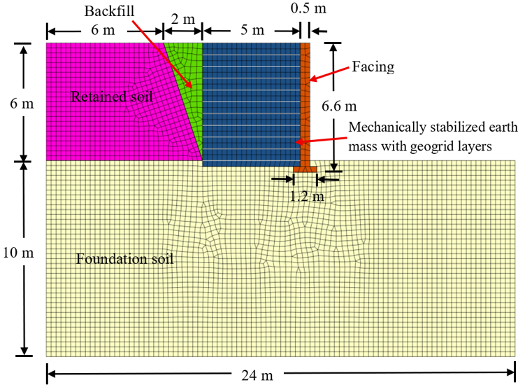
Figure 1. Geometry and finite element mesh of the reinforced earth wall model
Numerical Modelling
A two-dimensional reinforced earth wall was modelled in MIDAS GTS NX using both FEM and LEM. The same wall geometry, soil layers, reinforcement arrangement, and material properties were used in both analyses to ensure a consistent comparison.
In the FEM model, the soil domain was discretized using finite elements. In the LEM model, the same geometry was defined through surface assignments. The foundation soil, retained soil, and reinforced fill were modelled using the Mohr-Coulomb constitutive model, while the facing wall was represented as an elastic structural component.
Geogrid elements were assigned the same stiffness and tensile strength properties in both models. This approach ensures that any differences in the results arise from the analytical methodology rather than variations in the input conditions.
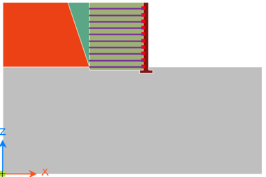
Figure 2. Reinforced earth wall model generated through surface assignment for LEM
Results and Discussion
The factors of safety predicted by FEM and LEM were within a comparable range. For the unreinforced case, FEM predicted a factor of safety of 1.60, while LEM predicted 1.47. With geogrid reinforcement, the predicted values increased to 1.81 in FEM and 1.93 in LEM.
Although the overall stability results were similar, the two methods identified the failure mechanism differently. FEM traced the probable failure zone through accumulated plastic strain during the strength-reduction process, whereas LEM searched for the critical slip surface corresponding to the minimum factor of safety.
However, do comparable factors of safety necessarily indicate the same failure behavior?
Author