Introduction
In this article, we will discuss why lateral torsional stability checks are mandatory during the erection, construction and service stages of steel girder bridges. We will also review the failure mechanism of LTB, evaluate how the geometry, loading and boundary conditions affect LTB and identify the scenarios where we can rule out the occurrence of LTB.
Supplementary to this article, we’ve validated the critical elastic buckling moment, Mcr obtained from Buckling Analysis in MIDAS CIVIL, as per the guidelines provided in NCCI SN003 (SCI,2005b)
Why is LTB Unsafe for Steel Girders?
Engineers may prefer steel over prestressed concrete for composite I-girder bridge construction due to a higher strength/density ratio, aesthetics, curvature of the deck etc. However, adopting slender steel I-sections comes with a unique set of challenges, which can lead to insufficient flexural capacity or even structural collapse if not taken care of.
As engineers, we dread any kind of “buckling” that could affect the structures we design, whether during the erection phase or their service life.
Let’s review a couple of past incidents where the collapse of steel girders could have been prevented if stability checks against LTB had been performed.
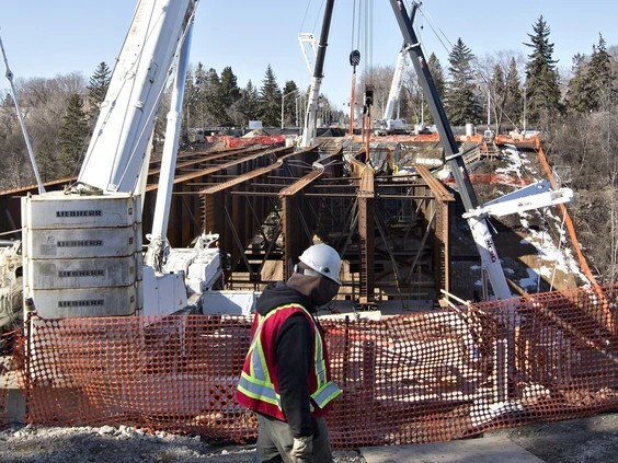
Figure 1: Buckling collapse of four steel I girders during erection, due to unbraced compression flanges
(Edmonton, Canada, 2015); Image Courtesy: The Canadian Press
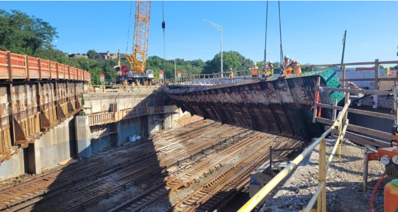
Figure 2: Buckling failure of the outer compound girder of an old bridge during maintenance works.
(Connecticut, USA ,2023); Image Courtesy: Metropolitan Transportation Authority
If you are curious to know why these steel girders buckled sideways under seemingly vertical loads, continue reading as we delve deep to understand the mechanics behind this instability.
But, first, let’s start with a question instead!
Imagine an I-section and a box section with the same cross-sectional area and second moment of area about their major axes. (assuming the wall thickness of the box section to be half the web thickness of the I-section)
Which of these sections would be more vulnerable to LTB?
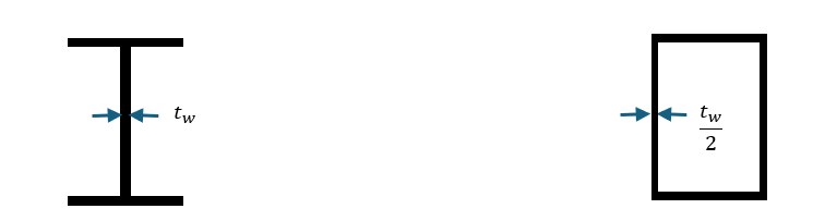
Figure 3: Two cross sections with same A and Iz
Hmm...you probably guessed it right!
We will revisit this question after reviewing the basics of buckling and LTB.
Basics of Euler’s Buckling
Consider a prismatic, centrally loaded column with pin-ended support, as shown below. When the applied compressive load, P reaches the elastic critical load, Pcr, the column tends to bow outwards, as shown using the dotted lines.
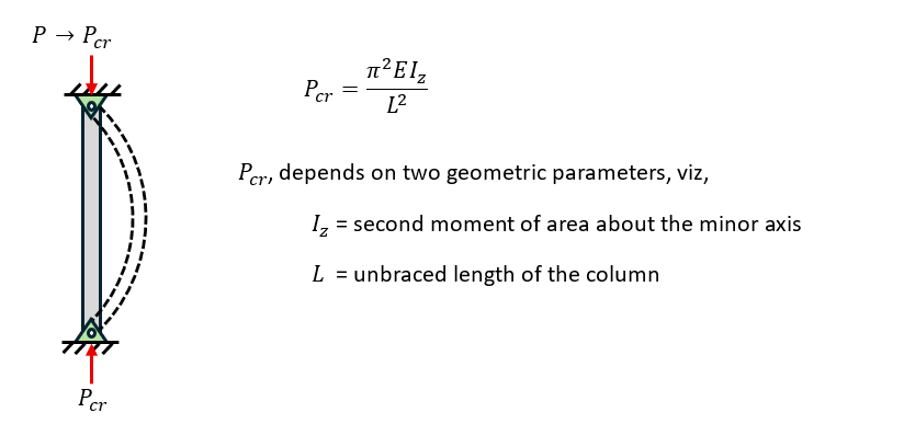
Figure 4: Euler’s buckling equation for a centrally loaded column with pin-ended supports
Unlike Euler’s buckling, LTB occurs in flexure, not compression.
Lateral Torsional Buckling
Now consider a beam under pure flexure, where the top half of the cross-section is in compression, and the bottom half is in tension.
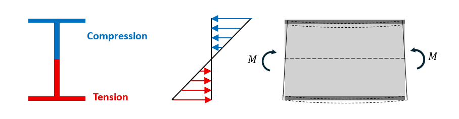 Figure 5: Stresses under pure bending
At failure, the top flange under compression tends to buckle laterally, while the bottom flange in tension tries to stabilize the beam by keeping it straight, causing a twist about the minor axis.
This instability of a laterally unsupported compression flange of a beam under flexure is called lateral torsional buckling.
As a rule of thumb, LTB is critical in beams whose second moment of inertia about the minor axis, Iz is significantly less than that about the major axis, Iy. However, that is not always the case!
Author