OVERVIEW
midas Gen and IDEA StatiCa interface allows you to utilize structural functions.
Let's get started on how to do the Steel Connection Design.
Step 1 : Checking the License for "Export IDEA"
Firstly, it is necessary to check whether the license for "Export IDEA" is supported.
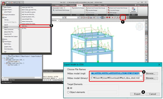
1) Run an analysis.
2) Run "IDA file..." in File > Export.
3) Modify the model names in a dialog box.
4) Click "Export".
Step 2 : Run IDEA StatiCa

 Run IDEA StatiCa
1) Click "Steel" tap.
2) Run "Import from other program".
3) Check on the options.
4) Click "Close".
Step 3 : Design Group

1) Click "Design Group".
2) Click the indicator 2.
3) Modify the group name and member type.
4) Modify the design members.
5) Click "OK".
Step 4 : Load Combinations

If there are the load combinations generated in Gen, these combinations are automatically applied.
1) Click "Result Classes".
2) Click "Combinations".
3) Add or Modify the combinations.
Step 5 : Joint Design - 1

[Joint Design]
1) Click "Joints".
2) Click "New".
3) Select the target Joint in the model window.
4) Click "OK".
5) Click "Design".
Step 6 : Joint Design - 2

[Joint Design]
1) Modify the member properties and position.
Step 7 : Joint Design - 3


[Joint Design]
1) Click "Apply" in Design tap > Template.
2) Select the connection detail in the template list.
3) Select the bolt type.
4) Click "OK".
Step 8 : Joint Design - 4

[Joint Design]
1) Modify the connection information.
2) Click "Code Setup" in Design tap > CBFEM.
3) Modify the factor values for design.
4) Click "Calculate" in Design tap > CBFEM.
Step 9 : Joint Design - 5


[Joint Design]
1) Click the "Check" tab.
2) Select the analysis result.
3) Select the element type.
4) Check the design result.
Step 10 : Reporting

[Reporting]
1) Click the "Report" tap.
2) Select the type of design report.
3) For BOM, Click "BOM".
4) Select the output type.
Step 11 : Drawing


[Drawing]
1) Click "DXF" and save as new name.
2) Import the dxf file in midas Drawing.


