
Composite Steel Integral Bridge Analysis and Design
**Please download the Webinar presentation under the Download banner at the end of the article**
Composite Steel Integral Bridges are quite popular for highway bridges spanning between 30m to 45m and with skew less than 30 degrees. Structural steelwork provides a lighter and quicker construction with adequate structural capacity. Integral bridges have the additional benefits of good ride quality, increased durability, and robust structural behavior.
With all the benefits of integral bridges, there are design challenges especially when it comes to the interaction of the structure with geotechnics. This article will discuss an example of a composite steel integral bridge, covering the analysis and design concepts used for such bridges.
Key Points
Key Point 1: How to decide on the various bridge parameters
The article discusses how the bridge geometry was decided, key construction parameters considered, and major determinants to selecting the foundation size and layout.
Key Point 2: What are the key loads to be considered in Integral Bridge Design
The webinar will discuss various scenarios of loading including the effect of thermal expansion and contraction in conjunction with earth pressure effects and different live load combinations acting on the bridge from the UK and Eurocode perspective.
Key Point 3: Analysis and Design Considerations
The webinar will discuss how to efficiently set up the analysis model to reflect a grillage deck, soil-structure interaction in the piles, and how to use the automated capacity calculation tools in MIDAS.
What is an Integral Bridge?
Conventional bridges have the superstructure supported on the substructure via bearings. The abutment behaves separately from the main bridge and there are expansion joints that separate the bridge from the approach road/embankment. Conventional bridges, therefore, allow for free movements of the deck under thermal expansion and contraction. In an integral bridge, however, there are no expansion joints to accommodate enlargement due to temperature variations and the bridge span is monolithic to the abutments. The following figures demonstrate the difference between a conventional bridge and an integral bridge.
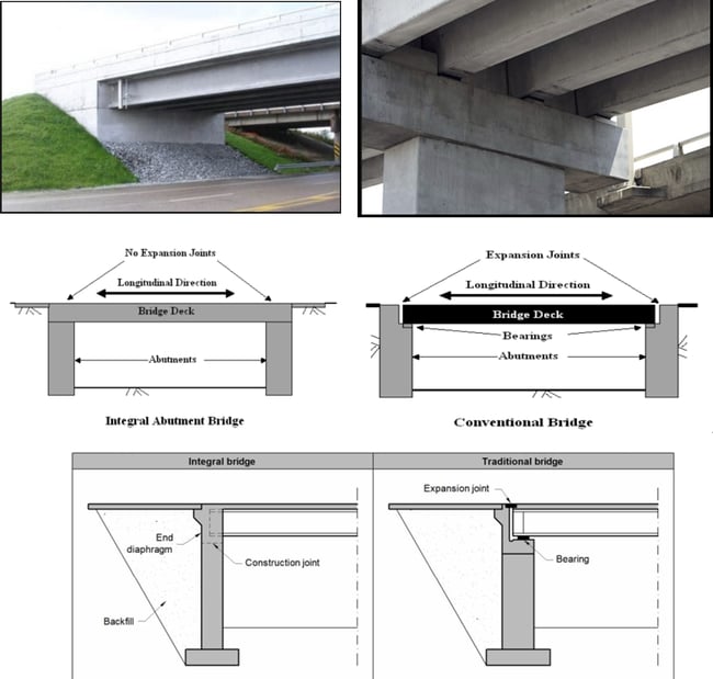 Integral abutment bridge vs. Conventional bridge
Why Integral Bridge?
Integral bridges are more durable than conventional bridges because of the continuity in the structure. There is no chance of leakage of salts through deck joints to abutments and piers. Integral bridges require lesser maintenance and fewer inspection problems. Integral bridges offer better structural performance, better Ride Quality, and better seismic performance. DMRB Standard CD350 states to go for integral bridge for spans<60m and skew<30 degrees.
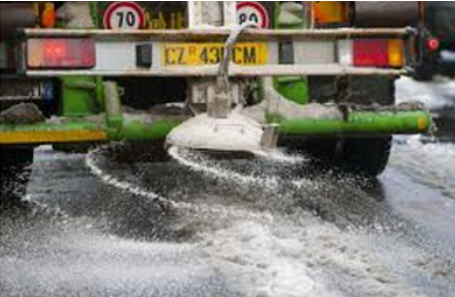 Chloride salt spray for deicing
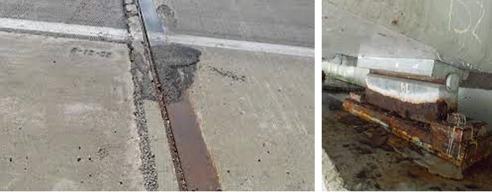 Typical expansion joint in decks and corrosion to bearing plates
Types of Integral Bridges
Integral bridges are of various types depending on the type of substructure supporting them. PD6694-1 shows that integral bridges resist the thermal contraction and expansion either through translation only or a combination of translation and rotation of the abutment. There are Frame type abutments that resist thermal movements using both rotation and translation of the abutment. There are bank pad abutments that are rigid and do not allow much rotation. In some cases, the earth (backfill) is separated from the substructure by using sleeves over piles or using reinforced earth walls.
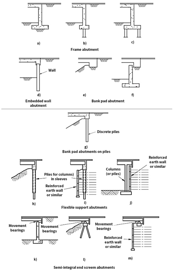 Types of Integral Bridges
Composite Action
Composite steel bridge deck typically constitutes steel plate girders with a concrete deck slab behaving monolithically. The deck slab acts compositely with the steel girders with the help of shear stud connectors. The construction of such a bridge involves, the steel girders being simply supported and then concrete being poured on the formwork supported on the steel girders. The stresses due to dead loads of concrete and steel are locked into the steel section. Once the concrete hardens, the composite section will undergo stresses due to other superimposed dead loads, the live loads, thermal actions, etc.
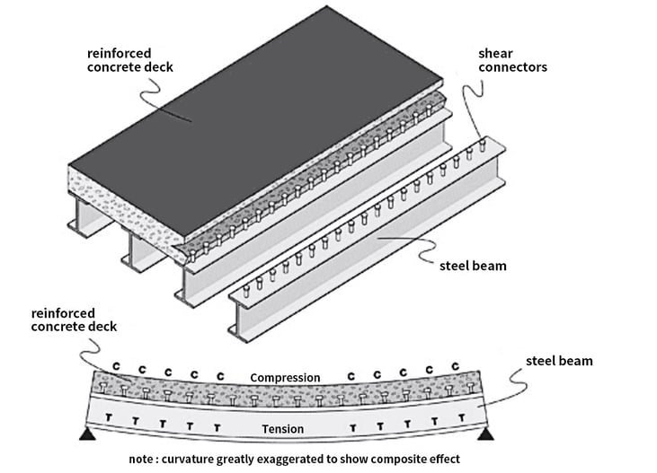 Typical Composite Action (Source: http://www.steel-bridges.com/composite-beam-bridge.html)
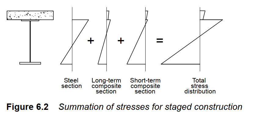 Stress buildup in Composite sections (Source: SCI P356)
Location of the Example Bridge
The example bridge is proposed at a location where a major motorway is facing an at grade junction which has led to congestion problems in the area. Therefore, the bridge is proposed to separate the grade at the junction and the bridge will cross over the existing motorway. The location is as shown below.
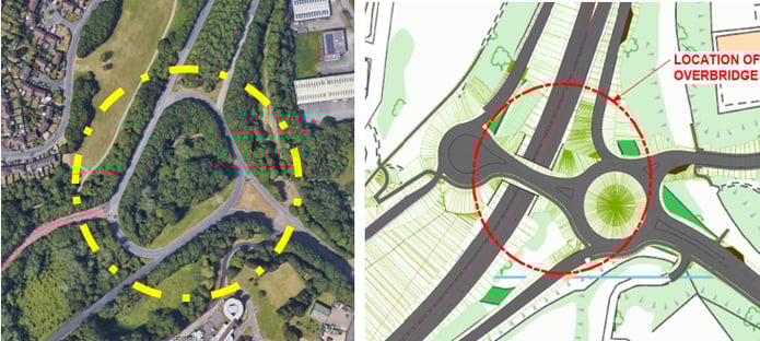
Structure Description
The bridge is a single span 31m structure (c/c of abutments), fully integral deck and abutment; separate wing walls, 8Nos. steel-plated I girders spaced at ~2.8m c/c. The deck is 22m wide carrying a 10m wide carriageway with a 5.7 degrees skew, 250mm thick constructed cast in-situ. The substructure comprises 9m tall reinforced concrete abutments supported by 2x8=16 RCC piles.
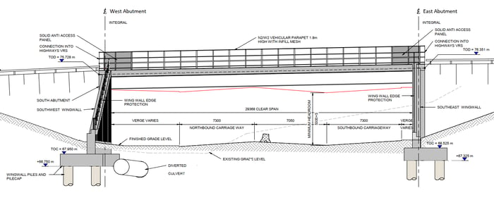 Elevation of the bridge
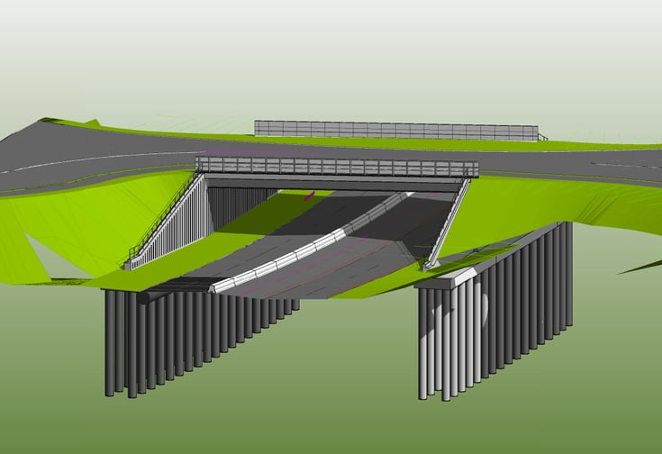 3D Rendered Model
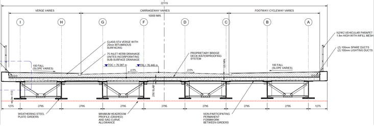 Deck cross-section
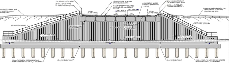 Sectional Elevation showing wingwalls, abutments, pile caps, and piles
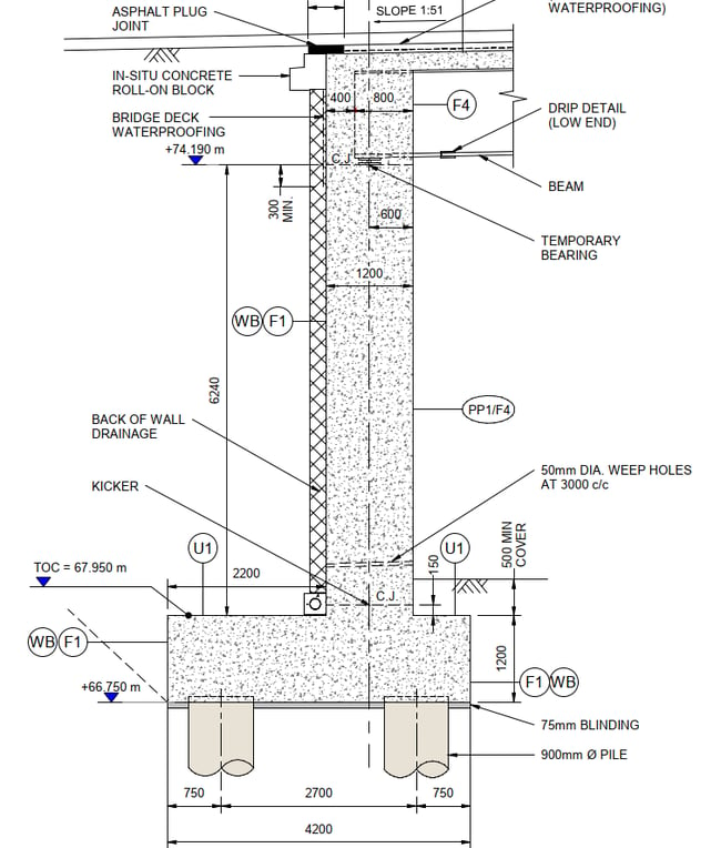 Section at abutment
Dimensioning of Steelwork
The first step of the design of the composite steel integral bridge is to dimension the steelwork. The dimensioning rules are derived from the Steel Construction Institute guidelines.
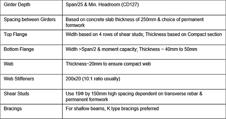
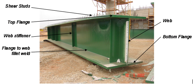 Components of a steel girder
.jpg?width=630&name=Typical-permanent-formwork-(Permadec).jpg)
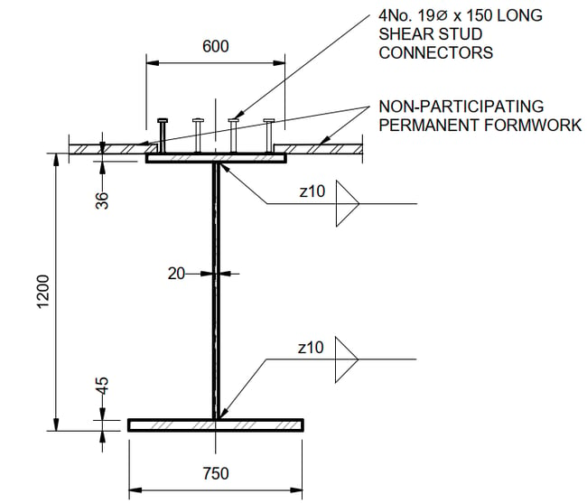
Steel section detail
Dimensioning of Concrete Elements
The next step of the design of the composite steel integral bridge is to dimension the concrete elements of the bridge including the deck slab, abutment, pile, and pile caps. The dimensioning rules are derived from the Steel Construction Institute guidelines and Eurocode detailing norms.
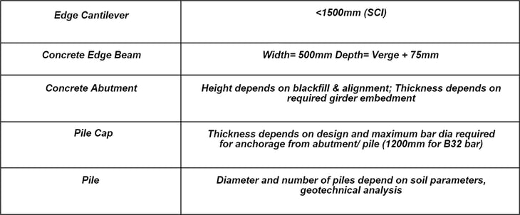
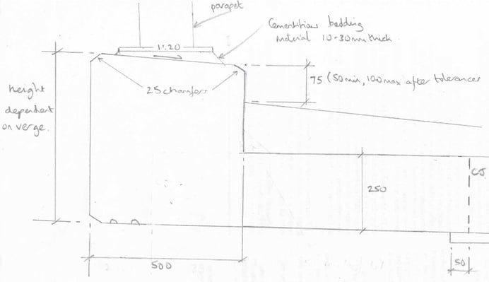 Parapet edge beam detail
.png?width=692&name=Girder%20end%20detail%20at%20integral%20abutment%20(SCCIP356).png) Girder end detail at integral abutment (SCIP356)
Girder end detail at integral abutment (SCIP356).png?width=650&name=Typical%20RC%20Detail%20of%20Pile%20Cap%20(IStrucE%20GuidE).png)
Backfilling
Another important point to consider is the sequence of filling earth i.e. backfilling the back of the integral bridge abutment. When the backfilling is done just after constructing the abutment but before placing the beams, the earth pressure at rest will act on the cantilevering abutment wall leading to a bending moment and base shear. The increased bending moment at the base of the abutment will lead to a more significant pile foundation and an increase in the cost of the substructure. Whereas, backfilling the abutment after constructing the bridge deck i.e. integral abutment, the earth pressure at rest acts on the abutment that acts as a propped cantilever leading to a reduced bending moment on the abutment but will increase hogging moments and axial compression on the steel girders making the steelwork more expensive but making substructure lighter. Though the latter case seems more reasonable as an increase in steelwork weight usually is less expensive than an increase in the size of the pile foundation. However, in this case, the first case was selected due to contractor preference as it was preferred to lift the steelwork from the back of the abutment.
%2c%20backfilling%20after%20integral%20connection%20(right).png?width=709&name=Backfilling%20before%20installing%20girders%20(left)%2c%20backfilling%20after%20integral%20connection%20(right).png)
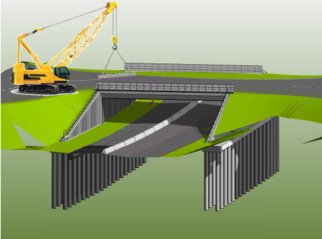 Approximate graphic showing intent of contractor
Global Structural Analysis
To analyze the global structure, a 3 Dimensional grillage model has been developed in midas Civil. The longitudinal members of the deck represent the Composite section. 15% of the span has been assigned with cracked slab properties longitudinally. The Transverse members comprise rectangular concrete section properties. The Abutment is modeled using Grillage elements (with dummy shells for pressure loads). The Pile Cap is modeled as a stiff pile cap with rigid links and the Piles are modeled as line elements applied with soil springs.
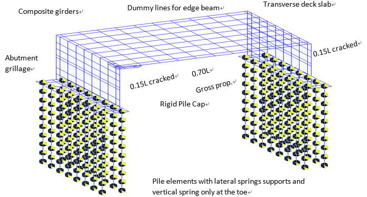
%3B%20composite%20girder%20section%20(righT).png?width=727&name=Modeling%20detail%20of%20pilecap%20and%20pile%20connection%20(left)%3B%20composite%20girder%20section%20(righT).png) Modeling detail in midas Civil
Modeling detail in midas Civil
Dead Loads and Superimposed Dead Loads
Dead load or self-weight applied in MIDAS using the self-weight functionality of MIDAS. Other Superimposed dead loads are applied with element beam loads and pressure loads.
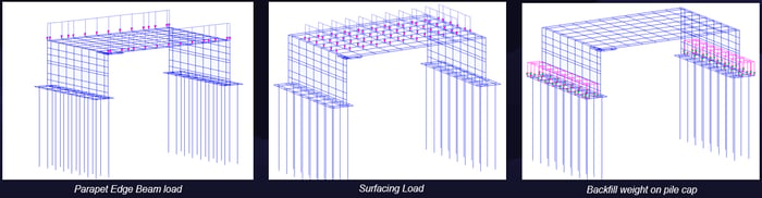 Dead loads and superimposed dead loads in midas Civil
Thermal Actions
The integral bridge does not allow any free movement of the deck and therefore thermal expansion and contraction cause stresses in the superstructure and substructure. 2 kinds of temperature loads are applied. The uniform temperature is applied using Element Temperature functionality in midas Civil whereas the nonlinear temperature gradient is applied using beam section temperature.
%20Eurocodes.png?width=1194&name=Thermal%20Loads%20(Uniform%20+%20Differentail)%20Eurocodes.png) Thermal loads (Uniform + Differential), Eurocodes
Thermal loads (Uniform + Differential), Eurocodes
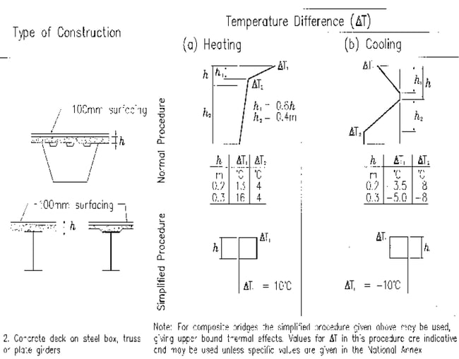 Differential temperatures to Eurocodes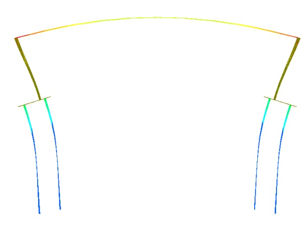
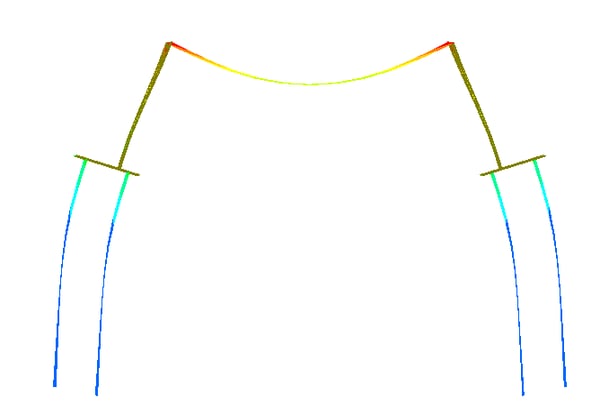 Deformations under thermal contraction
Earth Pressure
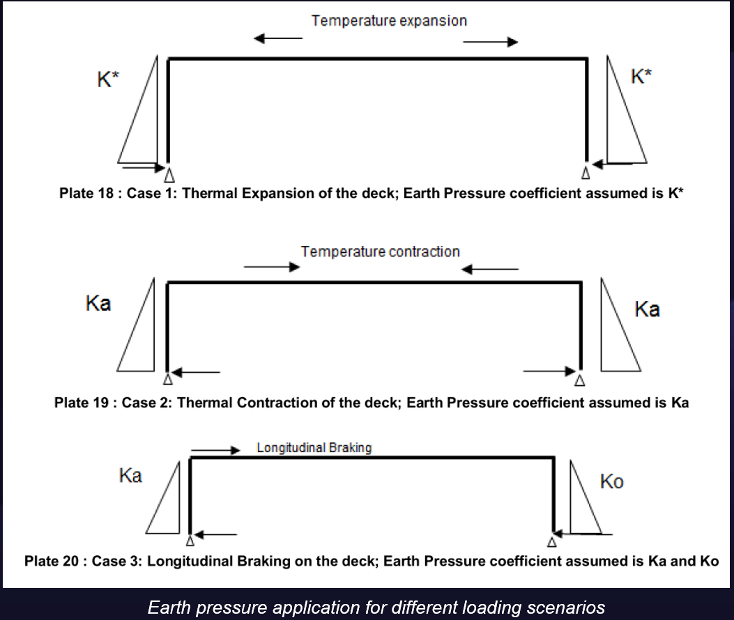
The earth pressure is calculated using the method given in PD6694-1. There are various scenarios of loading that have been considered. In the case of the thermal contraction, the deck contracts, and the earth pressure acting on the abutment is active earth pressure, Ka. When the deck expands due to the thermal expansion case, the earth pressure is calculated using the K* coefficient from the PD6694-1. The third case involves an asymmetric loading where there is a braking or traction load at one end of the bridge leading to active pressure at one abutment and the other abutment with at-rest pressure. Also, before the deck is constructed the backfilling is done at the back of the abutment, and in this condition, the earth pressure at rest Ko is applied. All earth pressure loads are applied using hydrostatic pressure loads in MIDAS.
..jpg?width=735&name=Earth-pressure-Diagram-from-PD6694Earth-pressure-applied-in-midas-(bottom)..jpg)
Traffic Live Loading
The traffic live load models are applied in accordance with the UK National Annex of BS EN1991-2 including Load Model 1, Load Model 2, footway pedestrian loading, Load Model 3 (SV100, SV19, and SOV250). The Moving Load Analysis feature in midas Civil has been used to perform influence line analysis and determine the most onerous vehicle load combination positions on the grillage model.
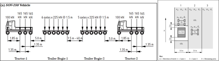
%20in%20midas%20Civil.png?width=735&name=Live%20load%20combination%20(LM1+SOV250)%20in%20midas%20Civil.png) Live load combination (LM1 + SOV250) in midas Civil
Live load combination (LM1 + SOV250) in midas Civil
Live Load Horizontal Surcharge
Horizontal Earth Pressure is generated due to Live load surcharge from vehicle loads near the abutment and that is calculated as per PD6694-1. The Live load horizontal surcharge is applied as Plane loads on the plate elements in midas Civil or as element beam loads applied over dummy elements.
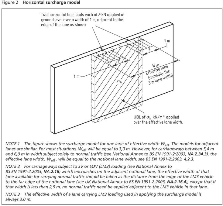 Figure from PD6694
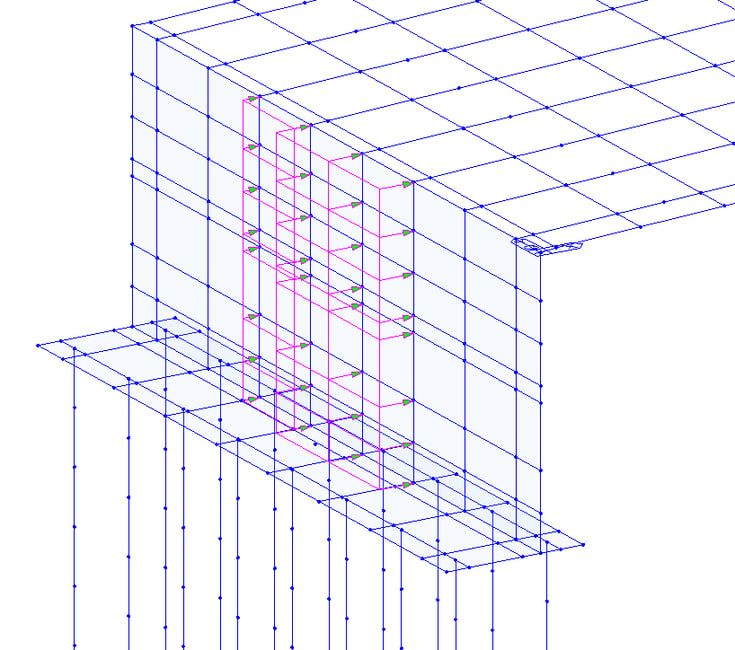 Horizontal live load surcharge applied in midas Civil
Construction Stage Analysis
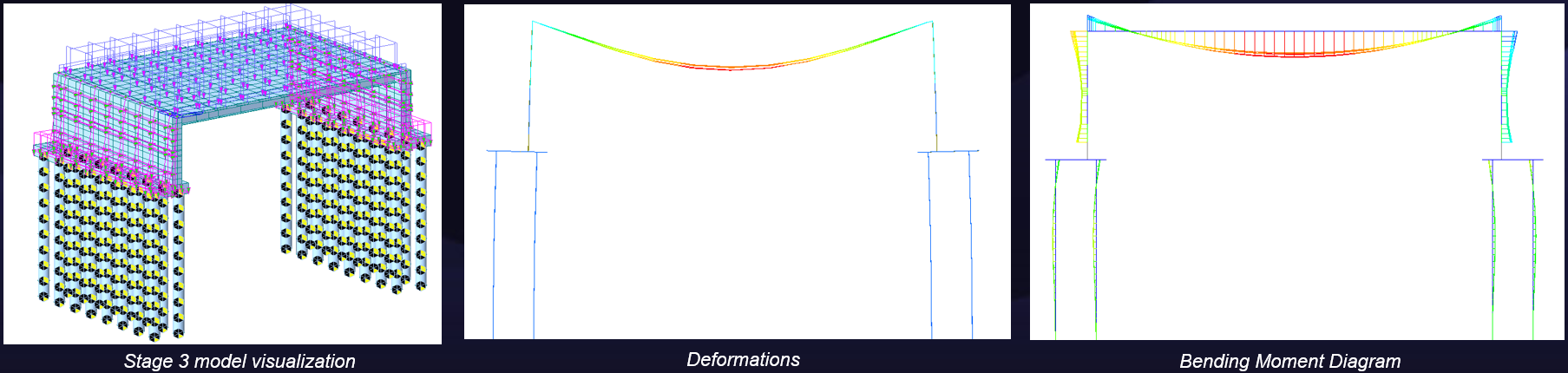
The construction sequence analysis is important for this type of bridge because of the changing loads, boundary conditions, and section properties of the elements. The earth pressure at rest acts before the steel girders are in place. The steel girders will be placed as simply supported beams on the abutment which will later become integral with the abutment and the longitudinal section properties will become composite. The various stages of construction are shown below.
Stage 1:
- Construct piles, pile caps, and abutments
- Apply backfill
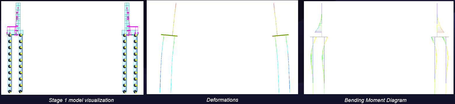
Stage 2:
- Install steelwork on temporary bearings (simulated as beam end released in midas Civil)
- Pour wet concrete on formwork supported on steelwork
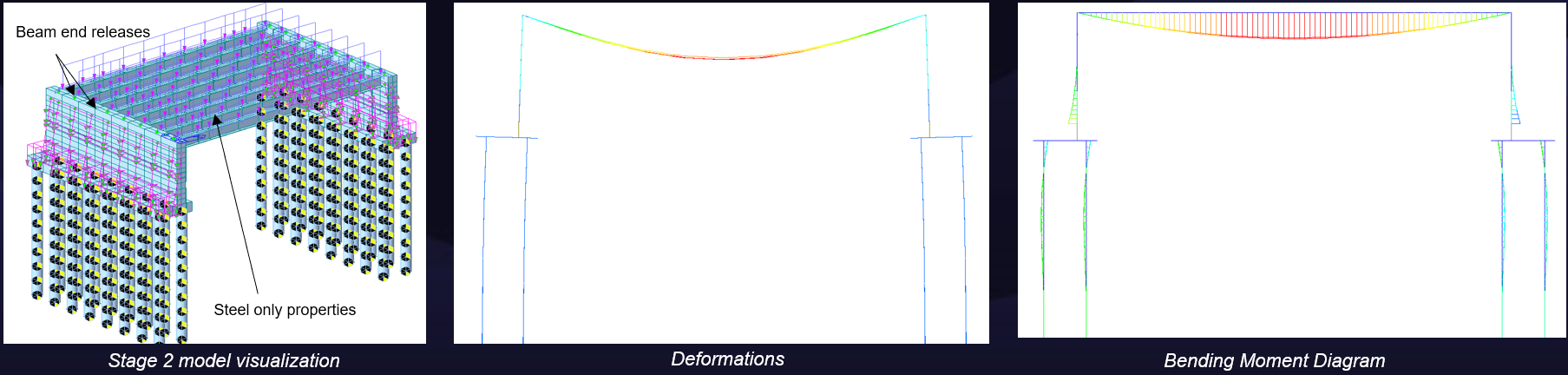
Stage 3:
- Concrete becomes composite
- SDL and surfacing activated
- Concrete long-term elastic modulus activated at later days
Composite Steel Design Checks
Midas Civil was used to carry out the global longitudinal steel girder capacity checks to EN1994-2. The bending resistance, shear resistance, longitudinal shear connector, fatigue checks are carried out using the midas Civil.
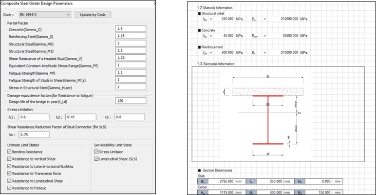 Built-in Eurocode features and detailed calculation output from midas Civil
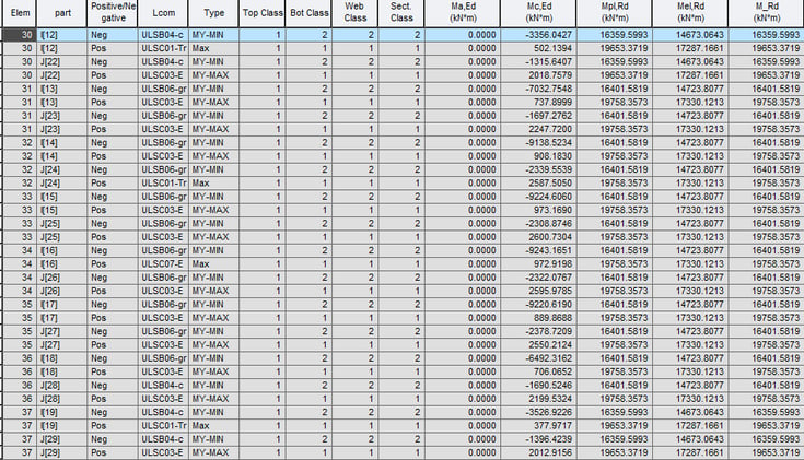 Summary results table generated from midas Civil
Steel Buckling Checks
During the temporary condition when the steel girders are simply supported and the concrete is poured over the formwork, the steelwork is susceptible to buckling. Also, the bracings are to be checked for impact loads. Both these checks require conducting a finite element analysis with shell (plate) elements.
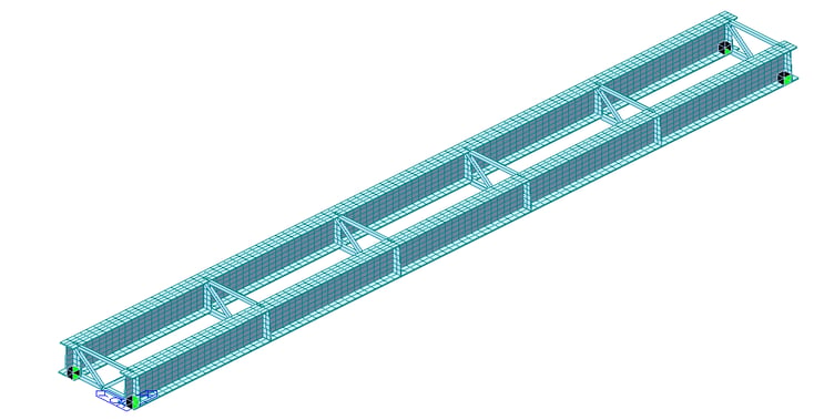 Finite Element Model with simply supported pair of girders
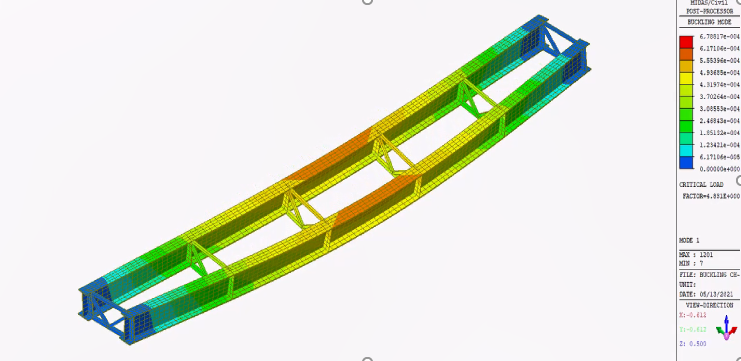 Linear Buckling Analysis: Lateral torsional buckling mode
Transverse Slab Analysis
Transverse Reinforcement in the deck slab has been calculated using a local line beam model with a continuous beam approach with steel girders simulated as vertical supports. The global effects of dead loads in the slab is considered by taking differential deflections between 2 adjacent girders taken from the global grillage model.
 Line beam model for slab
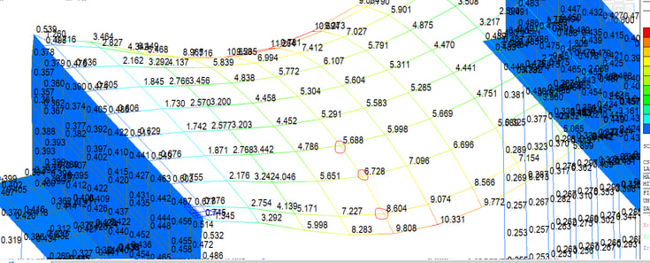 Differential Settlement between girders
Reinforced Concrete Capacity Checks
Reinforced concrete elements like abutments, wingwalls, piles, and pile caps are checked using simple spreadsheets as per Eurocode 2. The pile design has been done using an iterative process with geotechnics. The pile cap total loads are shared with the Geotech team to run a 2D nonlinear analysis in Geotech software to provide the structures team with soil springs which were rerun in midas civil to arrive at revised pile cap loads. The revised pile cap loads yield a new set of pile forces from Geotech. Pile Cap is designed as a strut and tie model as shown in the images below.
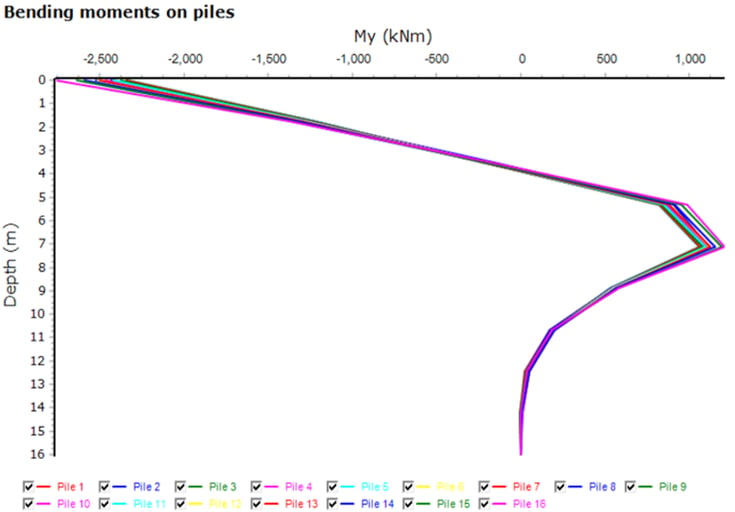 Pile bending moments from Geotech
.png?width=681&name=Pile%20cap%20idealisation%20(Concrete%20Centre%20Design%20Guide).png) Pile cap idealization (Concrete Centre Design Guide)
Pile cap idealization (Concrete Centre Design Guide)
MIDAS Expert Webinar Series Video




.png)