Section Stiffness Scale Factor
Contents
1. What is the Effective Moment of Inertia?
2. How to use the Section Stiffness Scale Factor in midas Civil
3. Effective Moment of Inertia Calculation Example according to AASHTO LRFD
1. What is the Effective Moment of Inertia?
midas Civil provides a Section Stiffness Scale Factor that allows users to change the stiffness of a section. This function can be used when engineers need to adjust only the stiffness value at the construction stage or when the effective moment of inertia needs to be considered in seismic design.
When considering seismic design through elastic analysis using a Response Modification Factor (AASHTO LRFD 3.10.7), it is reasonable to use the effective stiffness (AASHTO LRFD Seismic Bridge Design 5.6). In addition to AASHTO LRFD, the effective moment of inertia is described in various design standards such as ACI, Eurocode, Caltrans, and ATC-32, and computational methods are presented based on experimental results and theoretical approaches, respectively. For example, the Eurocode uses the stiffness corresponding to the theoretical rebar yield point on the moment-curvature curve. AASHTO LRFD, ACI, ATC-32, and Caltrans present effective stiffness considering the effect of cracking.
This blog content will introduce how effective stiffness can be applied in structural analysis and modeling using midas Civil. Furthermore, we have provided an excel template that can manually calculate the gross moment of inertia and the ratio of the effective moment of inertia using the AASHTO LRFD and ACI codes.
2. How to use the Section Stiffness Scale Factor in midas Civil
[Properties > Section Manager > Stiffness]
The Section Stiffness Scale Factor can be applied to a particular section to manipulate(increase/decrease) the sectional stiffness data considered for analysis. It is useful in various cases when performing Cracked Sectional Analysis, Rehabilitation, Stiffness Deterioration, etc.
For example, let’s check the results with and without the Section Stiffness Scale Factors of a 10kN/m Uniformly Distributed Load (UDL) applied to a Simply Supported Beam of 20m length and a 0.5mx0.5m rectangular cross-section. Here we will reduce the Iyy flexural stiffness by 50%.
The actual section stiffness is shown in the figure below.
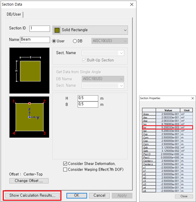 Figure 1: Section Stiffness and Calculation Results
Then, the reduced section stiffness data can be applied by following the procedure below.
[Properties > Section Manager > Stiffness]
.png?width=732&name=image%202%20(Section%20Manager).png)
As we do not have construction stages, and the Boundary group is set as “default,” these Stiffness scale factors will be applied for the entire analysis.
PFA two comparison models. Now Let’s compare various results of both the models.
Deformed Shape Results:
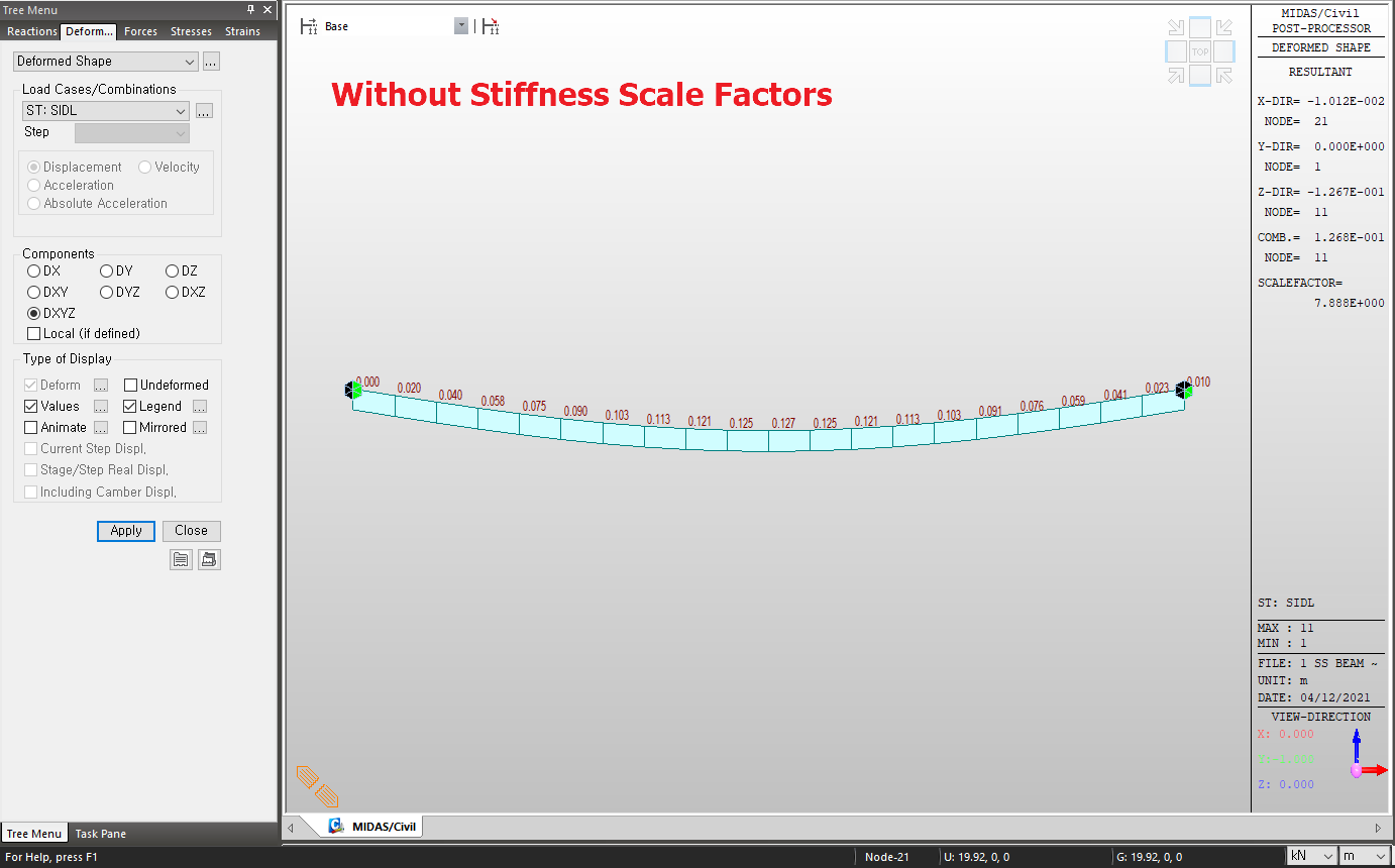 Figure 3: Deformed Shape Results WITHOUT Stiffness Scale Factors
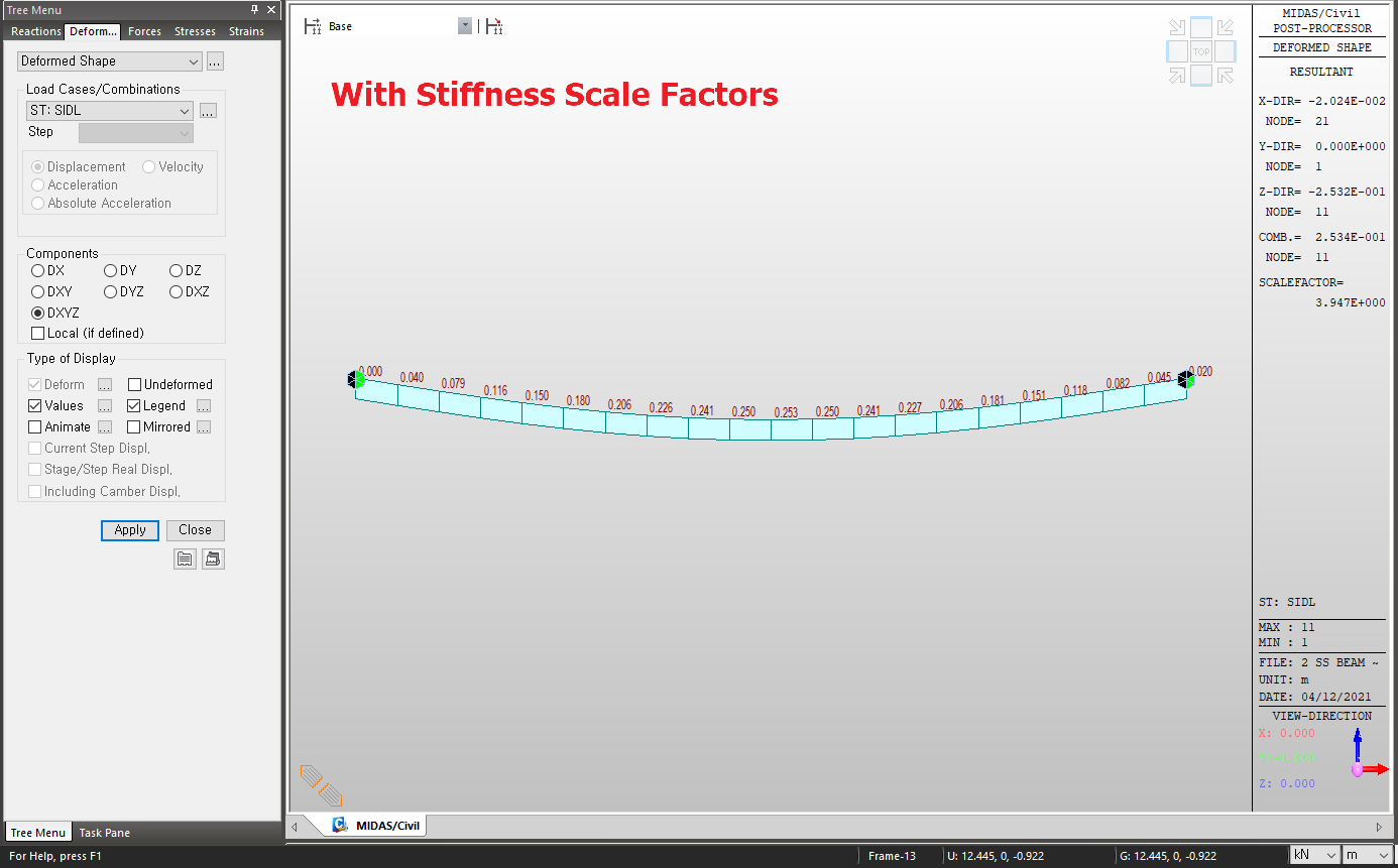 Figure 4: Deformed Shape Results WITH Stiffness Scale Factors
 The Scale factors defined here are applied to the calculations for displacements and member forces. For stress calculations, original section properties are used. However, the option for applying the Section Stiffness Scale Factors to Stress Calculations may be selected in Analysis > Main Control Data.
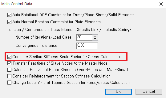 Figure 5: Main Control Data
Stress Results:
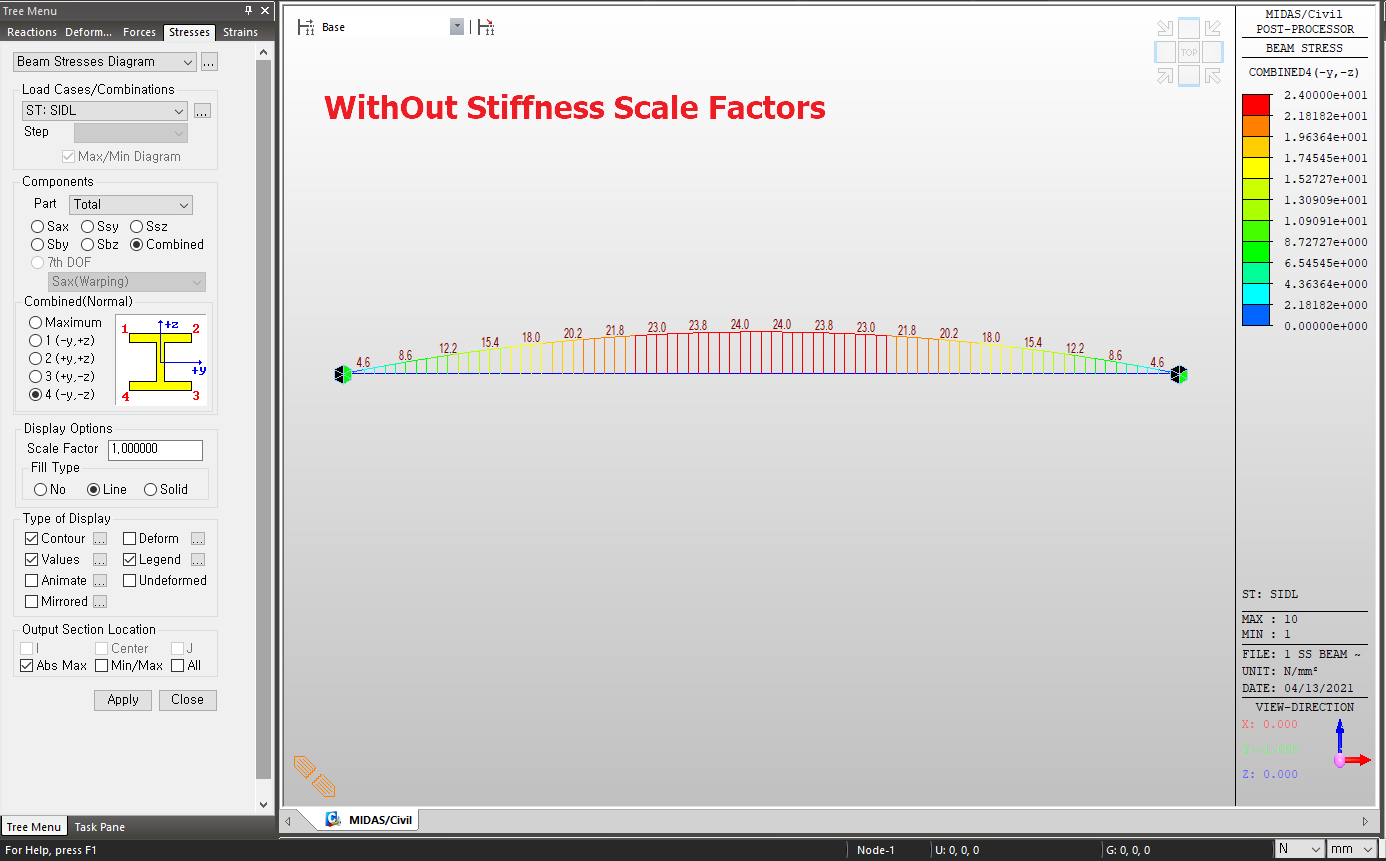 Figure 6: Stress Results WITHOUT Stiffness Scale Factors
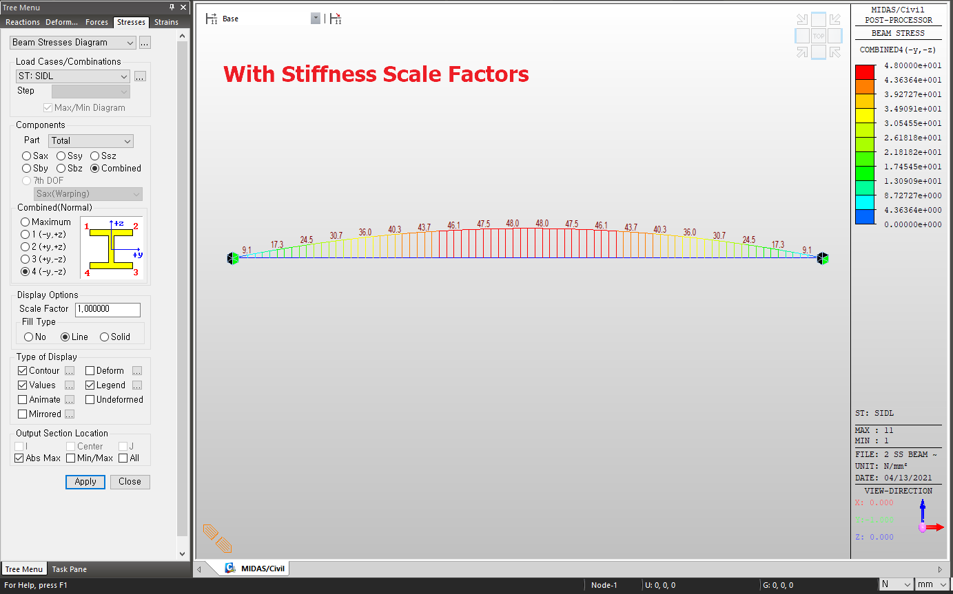 Figure 7: Stress Results WITH Stiffness Scale Factors
Suppose Construction Stage (CS) Analysis is involved in the model, and we want to apply these factors in CS analysis. In that case, we need to activate the Section Stiffness Scale Factors in the respective construction stages using the relevant “boundary groups” option.
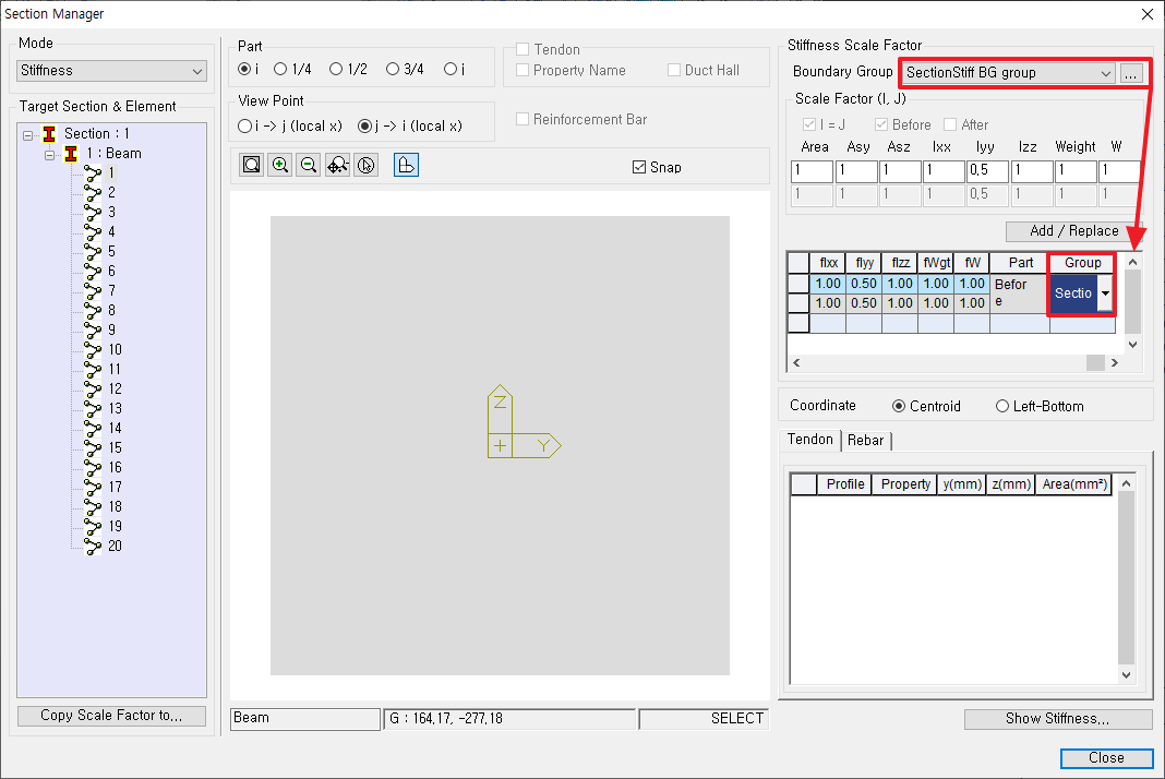 Figure 8: Section Stiffness Boundary Group Option
3. Effective Moment of Inertia Calculation Example According to AASHTO LRFD
Please look under the DOWNLOAD section below to download midasBridge "Effective Moment of Inertia for Circular Section Calculator" excel template. By entering the dimensions of the structure to be designed, the reinforcement information, and the loads, the user can calculate the ratio of the effective moment of inertia and the gross moment of inertia using the “Goal Seek” option in the Excel Template. The design basis report/national annex should be reflected in the design first, and we recommend users use the calculated values from the Excel Template as a reference.