Introduction
The capacity calculation of Reinforced Concrete Beam as per IRS Concrete Bridge Code for different stress blocks is explained in this article.
Analysis of sections
When analyzing a cross section to determine its ultimate moment of resistance, the following assumptions shall be made:
(1) The strain distribution in the concrete in compression and the strains in the reinforcement, whether in tension or compression, are derived from the assumption that plane sections remain plane;
(2) The stresses in the concrete in compression are either derived from the stress-strain curve in Fig.1 with gm = 1.5 or, in the case of rectangular sections and in flanged, ribbed and voided sections where the neutral axis lies within the flange, the compressive strength may be taken as equal to 0.4 fck over the whole compression zone. In both the cases the strain at the outermost compression fibre at failure is taken as 0.0035;
(3) The tensile strength of the concrete is ignored; and
(4) The stresses in the reinforcement are derived from the stress-strain curves in Fig. 4 with gm = 1.15. In addition, if the ultimate moment of resistance, calculated in accordance with this clause, is less than 1.15 times the required value, the section shall be proportioned such that the strain at the centroid of the tensile reinforcement is not less than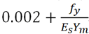
Where,
Es is the modulus of elasticity of the steel.
Stress Block
The distribution of compressive stress across the depth of concrete in compression is referred as stress block. The stress block may be assumed to be rectangle or parabolic which results in prediction of strength in substantial agreement with the results of test. A commonly used curve is that by various standards which consists of a parabolic for the initial ascending part followed by a horizontal straight line terminating at a prescribed ultimate strain, irrespective of the grade if concrete.
Fig.1 shows the cross section of a member subjected to bending and the resultant strain diagram, together with three different types of stress distribution in the concrete.
(1) The triangular stress distribution applies when the stresses are very nearly proportional to the strains, which generally occurs at the loading levels encountered under working conditions and is, therefore used at the serviceability limit state.
(2) The rectangular – parabolic stress block represents the distribution at failure when the compressive strains are within the plastic range and it is associated with the design for the ultimate limit state.
(3) The equivalent rectangle stress block is a simplified alternative to the rectangular – parabolic distribution.
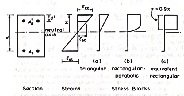
Fig.1: Section with strain and stress diagram (Reinforced concrete design by W.H.Mosley, J.H.Bunngey)
Rectangular – Parabolic stress block
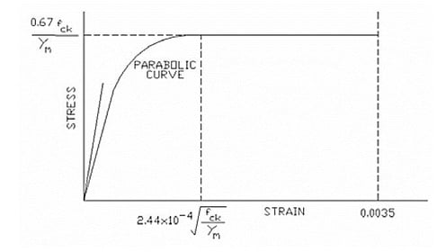
The behavior of structural concrete (Fig.2) is represented by a parabolic stress-strain relationship, up to a strain E0, from which point the strain increases while the stress remains constant. Strain E0 is specified as a function of the characteristic strength of the concrete (fck), as is also the tangent modulus of the origin. The ultimate design stress is given by

Where the factor of 0.67 allows for the difference between the bending strength and the cube crushing strength of the concrete, and ym = 1.5, is the usual partial safety factor for the strength of concrete when designing members cast in situ.
The stresses in the concrete in compression are either derived from the stress-strain curve in Fig.2 with gm = 1.5 or, in the case of rectangular sections and in flanged, ribbed and voided sections where the neutral axis lies within the flange, the compressive strength may be taken as equal to 0.4 fck over the whole compression zone. In both the cases the strain at the outermost compression fiber at failure is taken as 0.0035;
Equivalent Rectangular stress block
For the design of most reinforces concrete structures it is usual to commence the design for the conditions at the ultimate limit state, which is then followed by the checks to ensure that the structure us adequate for the serviceability limit state without excessive deflection or cracking of the concrete. Th simplified stress distribution will facilitate the analysis and provide more manageable design equations, in particulate when dealing with non-rectangular sections.
As a means of simplification, the IRS Concrete Bridge Code has suggested the replacement of the actual shape of the concrete compressive stress block (a second-degree parabola up to 0.002 and a horizontal branch up to 0.003) by an equivalent rectangular stress block, Fig. 3. This concept considerably reduces the computational efforts.
For sections without compression reinforcement the ultimate moment of resistance may be taken as lesser of the values obtained from the Eq. 1 and Eq. 2, whereas Eq. 3 and Eq. 4 may be used for sections with compression reinforcement.
A rectangular stress block of maximum depth 0.5d and a uniform compression stress of 0.4fck has been assumed (Fig.3).

Mu = (0.87 fy) As z ….. (Eq. 1, IRS)
Mu = 0.15 fck b d2 ….. (Eq. 2, IRS)
Mu = 0.15 fck b d2 + 0.72 fy As’ (d- d’) ….. (Eq. 3, IRS)
(0.87 fy) As = 0.2 fck b d + 0.72 fy As′ ….. (Eq. 4, IRS)
Where,
Mu ultimate resistance moment
As area of tension reinforcement
A ′ area of compression reinforcement
b width of the section
d effective depth to the tension reinforcement
d’ depth to the compression reinforcement
fy characteristic strength of the reinforcement
z lever arm
fck characteristic strength of the concrete
The lever arm, z, in Eq. 1 may be calculated from the equation:
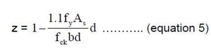
The value z shall not be normal taken as greater than 0.95d.
The ultimate moment resistance of a flanged beam may be taken as the lesser of the values given by Eq. 6 and Eq.7, where hf is the thickness of the flange.
Mu = (0.87 fy) As (d- d’) ….. (Eq. 6, IRS)
Mu = (0.4 fck) b hf (d- hf/2) ….. (Eq. 7, IRS)
The sample design verification for Simple beam as per IRS concrete design formulations for Rectangular stress block are compared with design output from bridge analysis and design program Midas Civil based on parabolic stress block approach is attached for reference.
Rectangular beam design as per IRS Concrete Design using Midas civil
Sample calculations with Midas model (Download)
For same beam the moment of resistance calculated considering the formulae given in IRS Concrete Bridge design code.
In conclusion, the moment capacity calculated by both the approach has significant difference in the outputs. The rectangular stress block will give conservative results than the capacity calculated by parabolic stress block.