Please fill out the Download Section (Click here) below the Comment Section to download the Full Webinar PDF File
This 1-hour course will cover the moving load analysis and assessment design of a PSC girder bridge. Attendees will get many valuable tips on the common assessment design process of PSC bridges as per CS454.
In midas Civil 2020 v2.1, PSC bridge assessment as per CS454 has been newly implemented. During the online session, moving load analysis with All Model 2 and special vehicles will be demonstrated. Using the analysis results, assessment load effects and assessment resistances will be obtained, and they will be verified using adequacy factor and reserve factor. Ultimate limit state (flexure, shear, and torsion) and service limit state verification are provided in the tabular format and MS excel report.
Watch the full webinar video
This case study highlights:
1. Why we need Bridge Assessment
2. Introduction to CS 454
3. Consideration of Live Loads for Assessment
4. Assessment Verification in midas Civil
1. Why we need Bridge Assessment
Bridge assessment provides a measure of the adequacy of an existing bridge or a new bridge concerning current design loads. Environmental conditions and repetitive vehicle loadings can reduce the expected life span of the road bridges. This is the point where bridge assessment comes into the picture. To determine the strength or load carrying capacity of a bridge, it is necessary to have a complete description of the bridge as-built, any modifications since it was built, and its present condition. The load rating is the key tool for bridge assessment. Load ratings are expressed as a rating factor (RF) for a particular vehicle. The emphasis in load rating is on the live-load capacity and the approach of determining rating factors instead of the design approach of satisfying limit states. Load Rating for bridges is done at both the strength limit state and service limit state.
Purpose of Bridge Rating
Bridge load rating provides a measure of a bridge's ability to carry a given live load in terms of a simple factor, referred to as the rating factor. These bridge rating factors can be used to aid in decisions about the need for (1) load posting, (2) bridge strengthening, (3) overweight load allowances, and (4) bridge closers.
/PSC%20Girder%20Bridge%20Assessment%20as%20per%20CS454/Fig%201.png?width=628&name=Fig%201.png) Figure 1: Purpose of bridge Rating
Figure 1: Purpose of bridge Rating
Application of Load Rating
a. New Construction
When designing a new structure, it is required that RF≥1 for the design vehicles (ALL Model 1 & ALL Model 2 from the CS 454).
b. Changes in the below category in the existing bridge:
- Live loads
- Dead loads
- Physical condition
- Specifications
/PSC%20Girder%20Bridge%20Assessment%20as%20per%20CS454/Fig%202.png?width=690&name=Fig%202.png) Figure 2. Different cases for Load Rating
Figure 2. Different cases for Load Rating
2. Introduction to CS 454
CS 454 is the new standard used for the “Assessment of highway bridges and structures.” Through this document, the structural safety and serviceability of highway bridges and structures can be assessed. It also provides key information that is required to manage risks and maintain a safe and operational network. CS 454 shall be used to assess Highway bridges & structures (Steel, Concrete, Wrought Iron, and Slab Bridges) and brick & stone masonry arches.
Overview
- Revision 0 of CS 454 was released in June 2019 and after that in Mar 2020, it has been updated with release of Revision 1.
- It supersedes existing standards like BD 21/01, BA 16/97, and BD 37/01 and also includes the following points :
- Inclusion of wind, thermal, and HB load models in new appendices, previously in BD 37
- Traffic load models for loaded lengths greater than 50 m, previously in BD 50
- Increase in the lane width for ALL model 1 (based on real vehicles) in the single-vehicle load case
- In addition to CS 454 the following codes also need to be used together for the assessment process.
- CS458(Special vehicles (STGO, SO)), replaces BD 86/11
- CS455(Assessment of concrete bridges), replaces BD 44/15, BA 38/93, BA 40/93, BA 51/95 and B A 52/94
/PSC%20Girder%20Bridge%20Assessment%20as%20per%20CS454/Fig%203.png?width=729&name=Fig%203.png) Figure 3: Codes for Bridge Assessment
Figure 3: Codes for Bridge Assessment
Assessment Process
The following chart shows the assessment process available in CS 454. In this case study, major focus would be on the “Assessment Calculation” part.
/PSC%20Girder%20Bridge%20Assessment%20as%20per%20CS454/Fig%207.png?width=547&name=Fig%207.png)
Assessment Live load
In the new standards and also even for the existing standard on the bridge assessment, loads could be classified into these 3 types:
-
1. Normal Traffic
- ALL Model 1 & 2 (CS 454)
-
2. Restricted Traffic
- ALL Model 1 (26, 18, 7.5, 3tonnes)
-
3. Abnormal Traffic
- STGO and SO vehicles
- HB load models
Here, Normal traffic would be considered for all the structures for the assessment. However, Restricted & Abnormal Traffic would be used only if required (As mentioned in clause 2.17.1) for the special cases and if required by the overseeing organization.
Clause 2.17.1 (CS 454):
“Where the structure is particularly vulnerable to actions other than those required in Section 5, the need to include them in the assessment should be agreed with the Overseeing Organization.
NOTE 1 Wind, thermal or longitudinal traffic actions can be critical for some types of structure, but can typically be neglected for common situations where the risk of such actions being critical for assessment is low.
NOTE 2 Assessment of highway structures for abnormal traffic loading (STGO and SO vehicles) is covered in CS 458 [Ref 7.N].
NOTE 3 The HB load models for abnormal traffic loading that were previously defined in BD 21 (withdrawn) for design are included in Appendix C for reference and for exceptional cases where an HB assessment is required by the Overseeing Organization.”
Level of Assessment
The level of assessment can be decided on the basis of the acceptable probability of the structure such that it can carry the traffic loads and does not suffer serious damage that can endanger any persons on or near the structure or cause loss of function. Suppose simple assessment is not sufficient to assure the safety of the structure. In that case, one needs to go for the higher level of assessment by performing the detailed structure analysis, including non-linear methods & field test results.
/PSC%20Girder%20Bridge%20Assessment%20as%20per%20CS454/Fig%208.png?width=666&name=Fig%208.png)
Typical Assessment Report (CS 451)
Contents:
- Introduction
- Structure Description
- Previous assessment summary with dates (include details of any strengthening works undertaken as a result of the previous assessment and revised capacity)
- Interim measures summary with dates
- Monitoring summary with dates (In accordance with CS 470[Ref 5.N])
- Assessment Inspection summary (Include text to identify and justify the condition factor used in the assessment calculations)
- Assessment method
- Assessment commentary
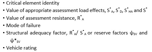
- Assessment result (Note: in addition to giving the overall assessed capacity of the structure, data should be presented about those elements that were critical to the assessment failure, including)
- Recommendations
- Assessment synopsis
Assessment Verification
The structure shall be deemed to be capable of resisting the assessment actions.
R*a >= S*a
Assessment Resistance:
R*a = FC (function of (fk, ȣm))
(CS 455 for concrete Structure)
Assessment Action Effects:
S*a = ȣf3 (effects of (Q*a))
Assessment Action:
Q*a = ȣfL Qk
Here,
FC = Condition factor
fk = Characteristic, nominal, or worst credible strength of the material
ȣm = Partial factor for material strength
ȣfL = Partial factor for each action (load)
ȣf3 = Factor that takes account of inaccurate assessment of the effects of actions such as unforeseen stress distribution in the structure, inherent inaccuracies in the calculation model, and variations in the dimensional accuracy from measured values
Adequacy factor & Reserve factor
Adequacy factor:
A = R*a / S*a
Special Vehicle reserve factor with standard vehicle:
Ψ = [R*a – (S*D + S*ST)] / S*
Special Vehicle reserve factor without standard vehicle:
Ψ* = (R*a – S*D) / S*
Here,
R*a = The assessment resistance
S*D = The assessment load effect due to combined dead and superimposed dead loads
S*ST = The assessment load effect due to the associated Type Standard vehicle loading
S* = The assessment load effect due to Special vehicle load model
S*a = The total assessment combination effect
3. Consideration of Live Load for Assessment
Assessment live loads, the normal vehicle is classified into two in CS 454:- All Model 1& All Model 2. Either of these two models can be used. Normally we expect all model 2 to be used for the general type of the bridges but if engineer expect All Model 1 would give more critical part then it also need to be verified.
ALL Model 1:
- This model is based on real vehicles with authorized weight.
- It shall consist of vehicle loads: Single vehicle or convoy of vehicles in each lane
- It is generally suitable for all structures
- Factors to be considered along with the vertical loads of the ALL Model 1:
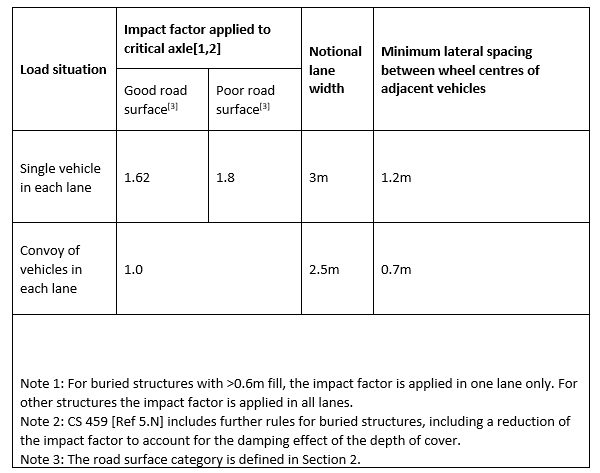
→ An impact factor applied to the most critical axle, obtained from Table 5.9a
(Impact factors and lane widths)
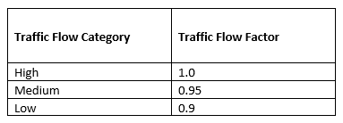
→ A traffic flow factor from Table 5.9b
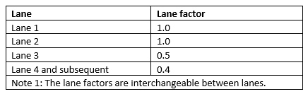
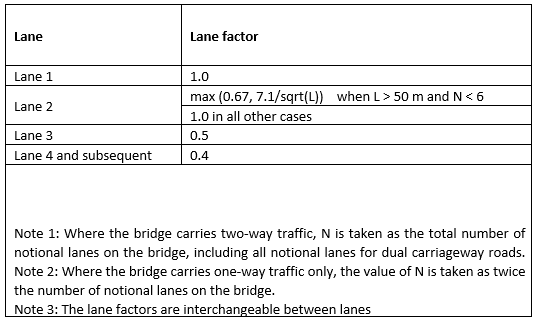
 → A Lane factor from Table 5.9c
The below table (Table B.1 Vehicle load models) contains axle weights and spacing for the critical vehicles in each of the assessment live loading levels.
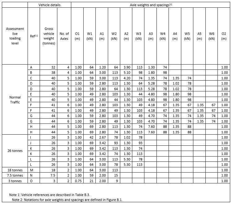
/PSC%20Girder%20Bridge%20Assessment%20as%20per%20CS454/Fig%204.png?width=467&name=Fig%204.png) Figure 4: ALL Model 1 – Vehicle Notation
Figure 4: ALL Model 1 – Vehicle Notation
ALL Model 2:
- The ALL model 2 shall consist of the following loads based on Type HA from BD21, applied separately:
→ A combined uniform and knife-edge load (Table 5.19a)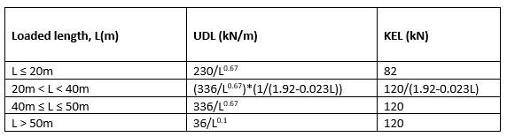
→ A single axle load
- This model is not suitable for certain situations (see cl.5.6):
→ Structures with transversely spanning trough decks
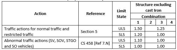
Application of ALL Model 2 with Special Vehicles:
Partial factors for actions (ȣfL) has been provided in Table A.1.
4. Assessment Verification in midas Civil
Midas Civil is a structural engineering software application used for bridge structural modeling, analysis, and design, including compliance checks for load testing and works with several civil engineering specifications. The CS 454 specifications for the bridge assessment have been implemented in the current version of Midas Civil.
The following chart shows the stepwise procedure of load rating in Midas Civil along with the feature explanation.
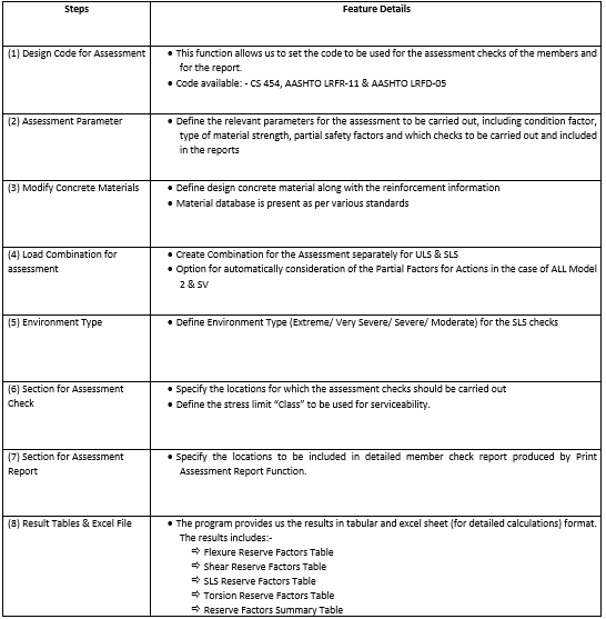
Results (Table Format):
/PSC%20Girder%20Bridge%20Assessment%20as%20per%20CS454/Fig%205.png?width=733&name=Fig%205.png) Figure 5: Table Format Results
Figure 5: Table Format Results/PSC%20Girder%20Bridge%20Assessment%20as%20per%20CS454/Fig%206.png?width=736&name=Fig%206.png)