🗂️ Download Now
Please fill out the Download Section below the Comment Section to download the complete guide to link elements.

1. STATIC FAILURE THEORY – DUCTILE MATERIALS
The main reason for observing stress is to determine if a part or structure fails. This article sees how parts fail under static or near-static loading and how to predict it. Part failure is affected by the part's geometry, its loads, and its material.
In general, shear strength limits ductile isotropic materials (Ductile Materials εmax >= 5%) in static tensile loading, and the tensile strength limits brittle materials.
There are several failure theories, but the two most reliable methods are:
- Von-Mises Stress ( Maximum Distortion )
- Maximum Shear Stress
Let's look at the Stress-Strain Curves in Fig.1
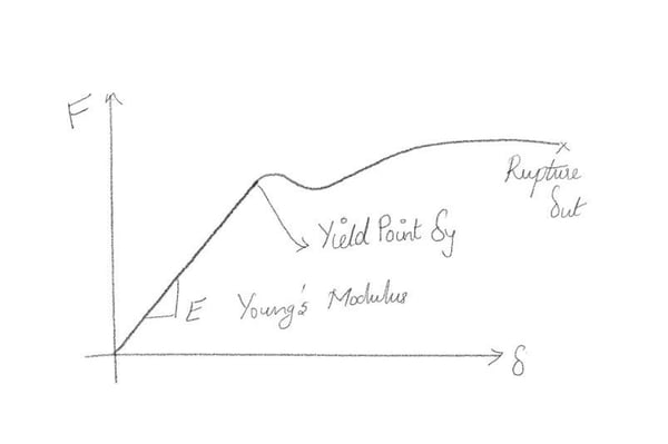
Frequently these curves are generated by placing a specimen in a machine and applying a tensile force until the material fails.
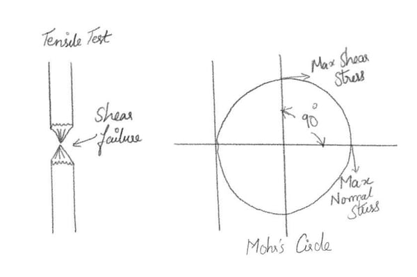 Figure 2. Tensile test & Mohr's Circle
The degree scale for Mohr's circle is twice what it is in the material. This is because the maximum Shear occurs 90o away from the Maximum Normal Stress but 45o away from the material.
2. Recollecting Terminologies
1) Hydrostatic Loading
Materials, though stressed beyond their ultimate strength, do not fail under hydrostatic loading.
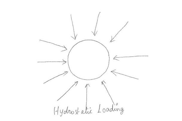 Figure 3. Hydrostatic loading
With hydrostatic loading, there is compressive stress (normal) but no shear stress. This leads us to suspect that when the parts fail, shear plays a strange role. It is related to the distortion n of the objects. It allows the molecules to slide next to each other in the structural lattice.
2) Strain Energy
Fig. 4 gives the relationship between stress-strain and energy.
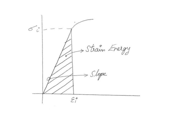 Figure 4. Strain Energy
The energy (U) at any point is:
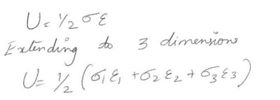
Using the relationship between stress and strain & substituting these into the equation for strain energy

We saw earlier that hydrostatic loading alone did not cause failure. Hence the strain energy can be divided and developed above into two parts, Hydrostatic & Distortion Energy.
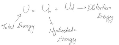
The stresses causing hydrostatic energy are the same in all directions so we can divide the principal stresses into:
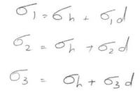
Adding these together yields:
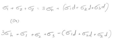
For volumetric change with no distortion, the terms in parenthesis must equal zero so

Now the Hydrostatic Energy (Uh) can be found. We know that hydrostatic stress is the same in all directions. Substituting in the total energy, one may obtain the Distortion Energy (Ud) as,
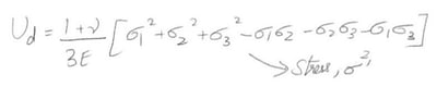
Using this, we set,
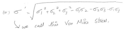
We call this the Von-Mises stress. It is based upon Distortion Energy, and it seems to be better at predicting failure than the other stresses.
3) Von-Mises Stress
Von-Mises effective stress is defined as the "uniaxial tensile stress that would create the same distortion energy as is created by the actual combined applied stresses".
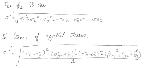 Figure 5. Von-Mises Stresses
Example
We have the following stress in a material, 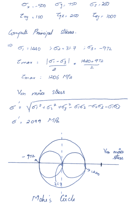
4) Safety Factor
If we define the safety factor as:
N = Failure Stress / Analysed Stress
This N value should always be larger than 1. It is usually significantly larger than 1.
1.3 <= N <= 5 or higher
1.3 when everything is known and carefully analyzed & 5 when there are many things unknown. For Von-Mises Stresses, the safety factor is computed with
N = σy / σ‘ = Yield stress / Von mises stress
3. Physical Significance of Von Mises Stress & Application in Steel Bridges
When we check the failure using the Von-Mises Stress, we are applying the Von-Mises yield criterion to determine to yield. Von Mises Stress Theory ( N = σy / σ ') is good for computing the Safety Factor against failure. Hence the material has to be checked if it fulfills the Von-Mises Criteria.
1) Application in Steel Bridges
Von Mises criterion is widely applied in the case of steel bridges and is the most preferred failure theory. Von Mises stresses are checked and ensure they are well within the elastic yield limit.
Consider a Bow-String Girder Bridge model in MIDAS CIVIL as in Fig. 7. The Yield Strength of the Girder of Material E250 is 250 N/mm2. Two cases are examined for Train Load and Double Track. The Stringer beam & the Cross Bracing at the mid-span as these elements are expected to experience maximum stress.
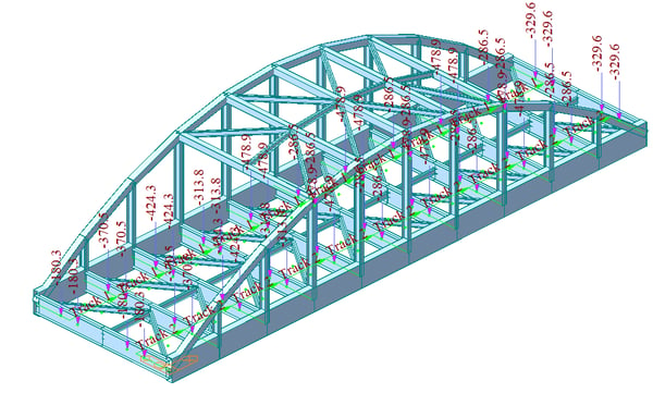 Figure 7. MIDAS CIVIL model of Bow-String girder bridge with applied train loads
The Von-Mises stresses can be obtained from MIDAS CIVIL, under Results > Stresses > Beam Stresses (Equivalent) > Von-Mises.
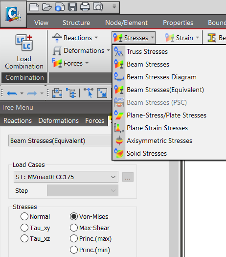 Figure 8. Von-Mises Stress option in MIDAS CIVIL model
The Von-Mises stress for the Stringer Beam near Mid Span (Dark Yellow Contour ) is 159 N/mm2, less than the Yield Strength value. Hence the design is SAFE. However, one may revise the section to consider a higher Factor of Safety.
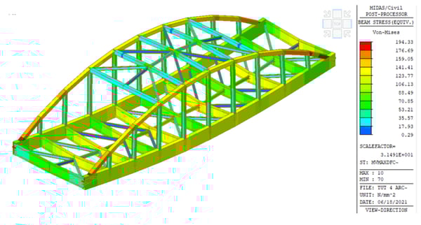 Figure 9. Von-Mises Stress for Stringer Beam near mid-span
The Von-Mises stress for the Cross Bracing near the mid-span (Pale Green Contour ) is 152 N/mm2, lesser than the Yield Strength value. Hence the design is SAFE. However, it is hard not to notice that the Von Mises for the Arch element near the support is greater than the Yield Strength, and one needs to revise the section.
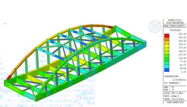 Figure 10. Von-Mises Stress for Cross Bracing near mid-span
In short, an engineer must keep the maximum value of Von-Mises stress induced in the material less than its yield strength.
Before Von-Mises's research looked at the tensile test of ductile materials, it was apparent that the failure was due to shear, not torsion. Both the Maximum Shear Stress Theory ( N = σys / τmax ) and Von Mises Stress Theory ( N = σy / σ ') are good for computing the safety factor against failure. However, the max shear stress theory is a little more conservative than the Von-Mises stress.
Note: The Maximum Normal Stress Theory ( N = σy / σ1 ) is not valid. Materials can fail even though N is greater than 1.