Contents
1. Introduction
2. Traffic Load Application to Produce Adverse Effects
3. Bridge Deck Geometry & Definition of Normal Traffic Loads
4. Loading Patterns
5. Recommendations
Introduction
Bridge structures are mostly subjected to dead loads and live loads. The permanent actions are of the dead loads such as self-weight, super-imposed loads. Live loads, which are traffic loads, acts on various possible positions on the bridge deck. The determination of traffic load position causing the adverse effects is not apparent and often needs specialized software or influence lines/surfaces.
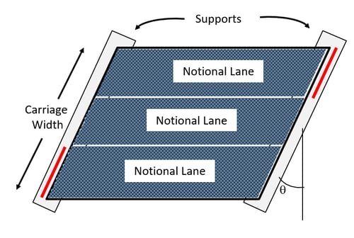
Furthermore, in skewed bridges, the abutments are not perpendicular to the bridge center-line. The acute angle between the abutment and the line perpendicular to the bridge deck's center-line is defined as the skew angle (θ), as shown in Fig.1. Extreme force effects due to live loads are generally reduced because of the skew; however, it produces the negative moments at the deck corners and torsional moments within the end zones and redistributes reaction forces at the supports. In a numerical model, accurate positioning of the design trucks in the bridge's transverse and longitudinal directions is vital to evaluate maximum live load effects.
 Figure 1: Skew Angle for a Bridge
Hence, we would require the Moving Load Analysis, typically a Static Load Analysis, to find the worst load effects of various possible positions along the bridge based on the Influence Line analysis or influence surface analysis.
Traffic Load Application to Produce Adverse Effects
Fully Loaded Bridge Decks do not necessarily cause the most adverse effects. At times, the relieving part of the deck could cause a critical effect as well. Codes specify only the magnitude of the load, leave us blindsided, and do not specify application patterns that cause the adverse effect for the live loading due to traffic loadings.
So the question arises, How the traffic loads should be applied to produce the most adverse effects?
For this, let us investigate the following:
- Can the set of standard application load patterns be used to approximate the most adverse effects of Live Loading?
- On using the standard patterns, how much will their results differ from the adverse load effects?
- Applicability of the standard loads when the skew angle of the bridge deck increases.
For this purpose, moving load as per The South African specification TMH7 is used. Only the Bridge Deck is modeled & analyzed for the critical normal traffic loading. Comparative finite element analysis to be performed with numerical modeling and analysis of single-span bridge deck under consideration, using midas Civil.
Bridge Deck Geometry & Definition of Normal (NA) Traffic Loads
Bridge Deck Geometry
The terminologies for carriageway, supports, and notional lanes are as follows:
Carriageway:
- The carriageway includes all the traffic lanes where actual traffic loads must be applied. Carriageway length = 15m Effective width= 10m
- Supports: Longitudinal supports below the carriageway restricting the vertical displacements.
- Notional lane: The longitudinal strips along the carriageway used to apply normal traffic loadings
Definition of NA Loading
NA Loading as prescribed by TMH7 consists of a distributed part & concentrated part acting in conjunction with each other.
Distributed Load
Load intensity of NA loading is given as,
for Le ≤ 36 m Qa = 36 kN/m
for Le > 36 m Qa = 180/√Le + 6 kN/m
where,
Le = effective loaded length (m)
Qa = intensity of the loading (kN/m)
NA loading is applied as two uniformly distributed line loads at 1.9m apart.
Concentrated Load
The associated Nominal Axle load is
144/√n kN
where
n = loading sequence number
Thus, if the loading in lane 1, 144/√1 = 144.00 kN
the loading in lane 2, 144/√2 = 101.82 kN, etc..
This loading is applied as two-point loads 1.9m apart.
Loading Patterns
Two loading patterns are compared, namely 'standard load pattern' and 'critical load pattern.'
Standard Load Pattern
Standard patterns are based on engineering judgment as to how an engineer could consider applying type NA loading to yield the most adverse effects in the absence of the influence-based software. As in figure 3, four cases presumed to cause the worst loading is considered. The concentrated axle is applied at left, center, right & one for torsional as well.


Critical Load Pattern
The loading pattern, as discussed above, loads the entire notional lane. This loading pattern ignores those regions, which may provide relieving effect when loaded. So for critical load patterns, those that generate critical positive or negative loading patterns are considered and are based on the influence value, at a chosen location, of a load increment as it moves over the notional lanes.
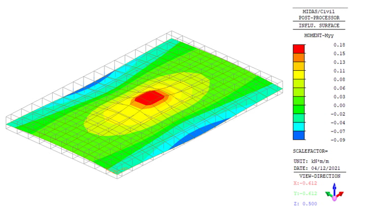 Figure 4(a): Influence Surface Bending at Center of Span
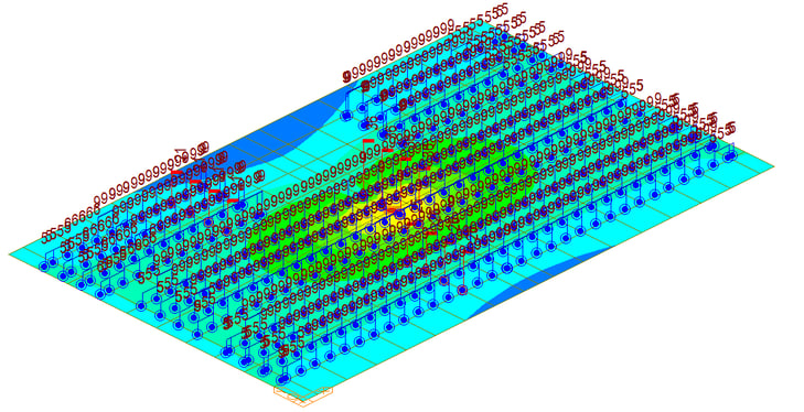 Figure 4(b): Application of the Critical Loading Patterns in midas Civil
The concentrated axle loads would be placed at the highest influence value in each moving load direction.
Vehicle Positioning in longitudinal direction alone is not sufficient. The transverse position also comes into the picture to determine particular critical positioning.
1. Regular optimization:
-
There are three positions for vehicle placements (at the center, extreme left, and extreme right of the lane). However, for NA and NC type vehicles, the transverse placement does not have much significant effect.
-
As per carriageway width, these three positions are sufficient to cause the worst effect.
 Figure 5: Vehicle Placement over Lane Width
2. Multi-point Optimization
- Tie settlement should be reviewed from the location where the extended nodal zone and the center of the ties meet.
-
The extended nodal zone refers to the area where each effective width overlaps at the location where the struts and ties meet.
 Figure 6: Multi-Point or Moving Load Optimization in midas Civil
Recommendations
Comparative Analysis
The results, such as the moment resultant by the standard load pattern & the critical load patterns, can be compared by varying the skew angle.
Critical NA loading patterns and resulting contours of the longitudinal bending moment at mid-span at the center of the carriageway
For Skew = 0o

For Skew= 10o
 For Skew=20o

For Skew= 40o

The Critical live load patterns do not follow any typical behavior for the longitudinal bending. As the skew angle increases, it is difficult to determine the regions of the bridge deck to be loaded for the adverse effects. For the twisting and transverse bending moment, the vehicle needs to be placed at all the critical locations to determine the adverse effects, which can be effectively captured using the moving load optimization function of midas Civil.
The interpretation stands valid for other codes or standards as well.
Reference: http://www.scielo.org.za/pdf/jsaice/v55n3/10.pdf