
Camber Control in midas Civil
Table of Contents
2. Understanding Construction Stage DisplacementsOversimplification for FEM Practitioners
1. Introduction
In bridge engineering, Camber refers to a pre-fabricated/pre-designed shape that enables the members to maintain a stress-free state for the member to reach a targeted shape at a specified time. Two main prerequisites that need to be set before calculating camber are:
a) Target shape and the time of the target shape.
b) Stress-free state.
For simple bridges, the target shape is considered as the reference state and camber calculations are straightforward. But, for long-span bridges, (like a cable-stayed bridge), the camber calculations are iterative as the camber will affect the deformations and stresses, thus causing a non-linear problem (Camber -> Deformation+Stress -> Camber).
Accurately calculating the camber by the designer is imperative and will serve as crucial data for the construction engineer, enhancing the serviceability and durability of the bridge especially cable-supported bridges.
2. Understanding Construction Stage Displacements
Construction Stage Analysis(CSA) is very much required to make real construction safe and serviceable. It is imperative to perform a detailed construction stage analysis for statically indeterminate structures having the loading history included in the analysis. Many factors affect the deflections in construction stages like Construction Process, Creep and Shrinkage, Prestress Losses, Time Delays, etc.
Three displacement results can be obtained from Construction Stage Analysis in midas Civil
a) Accumulated Displacement
b) Current Stage Displacement
c) Stage/Step Real Displacements
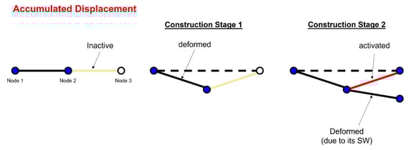
Accumulated displacements are the displacement results obtained by adding all stage displacements including the current stage displacements. The discontinuous point of the sawtooth shape exists since each segment upon creation has only the load influence accumulated (the load influence has not been accumulated before the creation of the segments).
In Figure 1, the first element is activated, and then it is deformed due to its self-weight, which means the center node is in a deformed location but in the next construction stage when the second element is activated the third node is activated in the modeled location. As a result, the elements form an angle even though there was no angle when the elements were initially modeled. Next, in construction stage 2, the second element will deform due to its self-weight.
Current Step displacements are the displacement results obtained only due to the loads/boundary changes acting in the current stage.
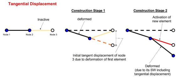
Tangential displacements are the displacements of the elements which will be created in the next stage considering the rotational angles of nodes resulting from each current construction stage. In Figure 2, the initial tangent displacement of node 3 is a result of the deformation of the first element in construction stage 1. Next, in construction stage 2, the second element is deformed such that it has the deformations of its self-weight and also includes the angular displacement created by node 2. In midas Civil, the initial tangent displacements are calculated by using the specified displacement function.
Let us see how midas calculates the deformation results in each CS stage with an example.
Consider a cantilever of 15m length built in three construction stages
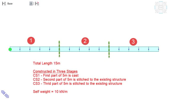
Figure 3: Cantilever constructed In three stages
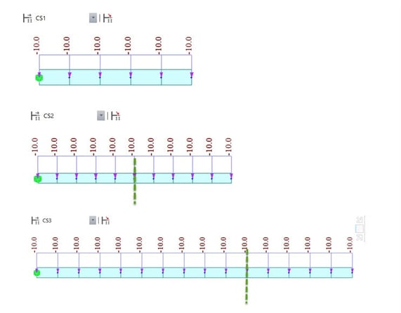
To simulate the above construction stages in midas, we have created three stages as shown below CS1, CS2, and CS3 (green dashed line indicates the construction joint).
Now the deformation results in each CS Stage are as follows:
Accumulated Displacements:
CS1 --> CS1 deformation = (current step Displ. of CS1)
CS2 --> CS2 deformation = (CS1 deformation) + (current step Displ. of CS2)
CS3 --> CS3 deformation = (CS2 deformation) + (current step Displ. of CS3)
Stage/Step Real Displacements:
CS1 --> CS1 Stage/Step Real Displ. = (current step Displ. of CS1) + (Tangent displacements)
CS2 --> CS2 Stage/Step Real Displ. = (CS1 deformation) + (current step Displ. of CS2) + (Tangent displacements)
CS3 --> CS3 Stage/Step Real Displ. = (CS2 deformation) + (current step Displ. of CS3) + (Tangent displacements)
Note: In midas Civil, If "Initial Tangent Displacement" is turned ON, then boundary conditions will be activated using stage/step real displacements, hence we need to be careful in using deformed or Original position while activating boundary conditions in construction stage definitions.
3. How Camber is Calculated?
Now we know the displacement output from FEM analysis software like midas Civil, we as a designer need to determine the camber/pre-camber that needs to be supplied to the construction engineer. To avoid confusion between the designer and the construction engineer, the ‘camber and related terminology’ have been summarized in below Table 1.
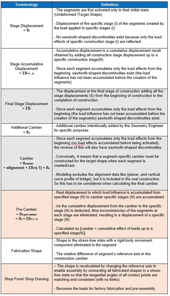
The Camber(δcamber) is provided when the construction method is using the cast-in-situ concrete (in this case, the fabricated shape and shop form do not exist as everything happens on-site).
The Shop Form(δN,pre-camber) is considered when the construction method uses prefabrication/precast techniques (in steel girders and precast concrete girders).
Construction Stage Analysis is necessary to arrive at the camber values based on the type of real construction of the bridge. Most of the structural analysis programs like midas Civil use the Finite Element Method(FEM) and this method sets the elements the initial state as an undeformed state/modeled location. This means that the segments/elements from the previous construction stage have the displacements but the segments/elements of the current construction stage do not have the influence of the previous construction stage, thereby the displacement at the final construction stage has discontinuity (saw tooth kinks). In cast-in-situ concrete construction the same happens as the current casting of the segment does not have load influence of the previous construction stages, hence, there is no need for stage/step real displacements here.
Alternatively, if precast/fabrication techniques(where the entire girder is match-cast in segments) are used then we need to calculate and include the stage/step real displacements in the camber calculations to avoid discontinuity.




-1.png)