Steel Composite Girder Flexural Capacity: AASHTO vs Eurocode
Table of Contents
1. Introduction
2. Flexural Resistance as per AASHTO LRFD
3. Flexural Resistance as per Eurocode
4. Comparison of AASHTO vs Eurocode Flexural Resistance
5. Conclusion
1. Introduction
Steel composite bridges are widely used due to the proper utilization of tensile strength of steel girder and the compressive strength of concrete deck, thereby bending resistance is greatly enhanced, making it more efficient and economical. Multi-girder system or ladder deck forms of steel composite bridges are the main forms of construction having simply supported or continuous girders.
In this article, design provisions for ultimate flexural resistance as per AASHTO LRFD and Eurocode are detailed. Flowcharts are shown for better understanding.
2. Flexural Resistance as per AASHTO LRFD
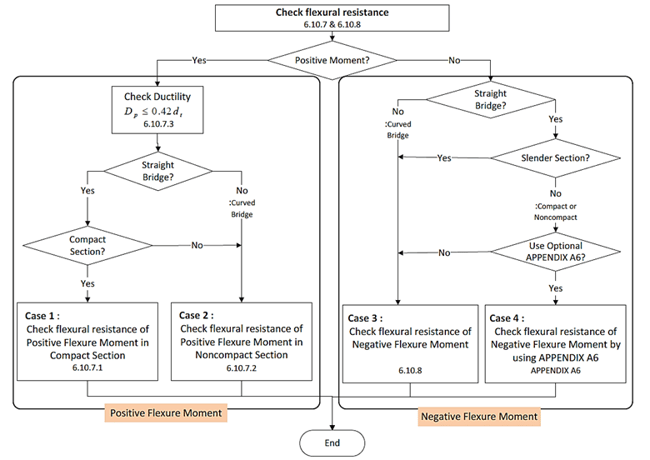
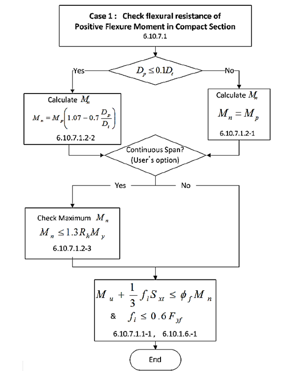
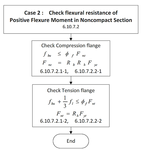
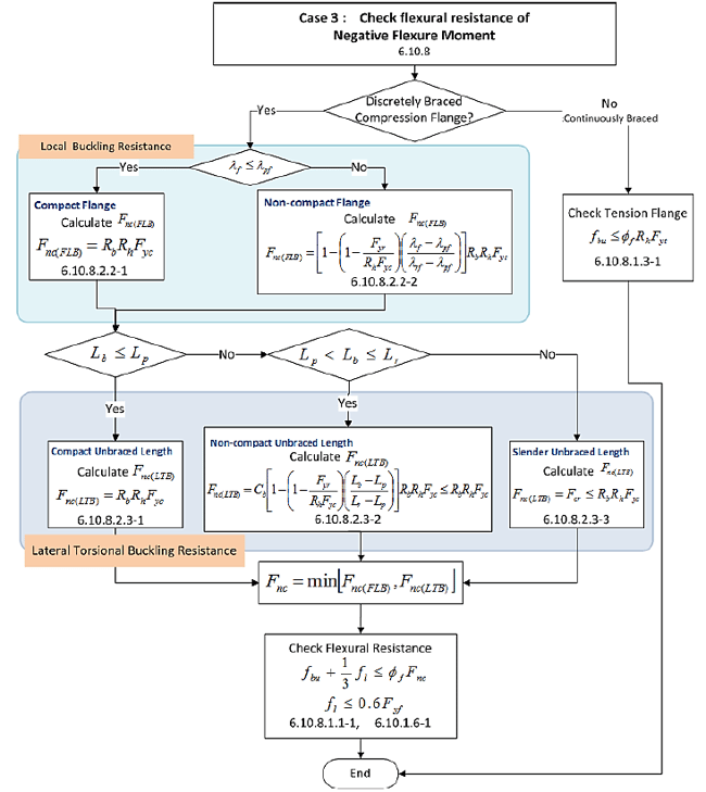
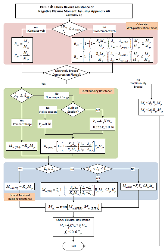
The procedure of calculating flexural capacity of steel composite I section is outlined in Figure 1, where four cases are established.
Case 1: Flexural Resistance of Positive Flexure Moment in Compact Section.
Case 2: Flexural Resistance of Positive Flexure Moment in Non-Compact Section.
Case 3: Flexural Resistance of Negative Flexure Moment.
Case 4: Flexural Resistance of Negative Flexure Moment by using Appendix A6.
3. Flexural Resistance as per Eurocode
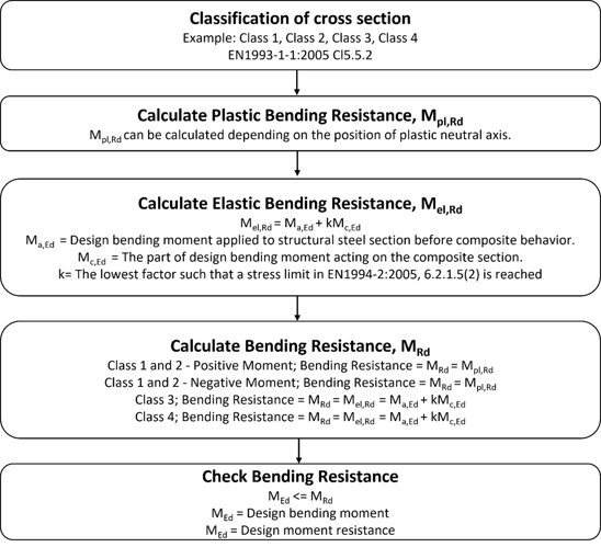
Bending resistance, MRd, can be calculated as follows based on its class.
Class 1 or 2 cross‐sections can be checked by using the plastic or elastic bending resistance.
Class 3 cross‐sections are checked with the elastic bending resistance, or possibly reclassified as effective Class 2 cross‐section and then checked with the plastic bending resistance.
Class 4 cross‐sections are also checked with the elastic bending resistance but by using the effective cross‐section, reduced to take account of buckling.
4. Comparison of AAHSTO vs Eurocode Flexural Resistance
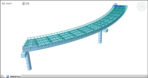
Let's take a 2-Span Steel Composite I girder Curved bridge for comparison.
Number of main girder: Four, Steel Composite I girder
Curvature radius: 4.318 m
Construction Stage Analysis: Yes
The bridge is modeled in midas Civil as shown below:
Keeping the materials, sections, and loading the same, the positive bending region was designed as per AASHTO LRFD-17 and Eurocode (EN1994-2). The results are illustrated in figure 8 where the flexural resistance checks are satisfied as per the codes.
|
|
AASHTO LRFD |
Eurocode |
|
Section |
|
|
|
Materials |
Steel fsk= 355.000 MPa Es=210000.000 MPa
Concrete fck= 30.000 MPa Ecm = 33000.000 MPa
Reinforcement fyk = 400.000 MPa Er = 210000.000 MPa
|
Steel fsk= 355.000 MPa Es=210000.000 MPa
Concrete fck= 30.000 MPa Ecm = 33000.000 MPa
Reinforcement fyk = 400.000 MPa Er = 210000.000 MPa
|
|
Region |
Positive Bending |
Positive Bending |
|
Demand Forces |
Steel only moment MD1 =2462 KNm
Long-term moment MD2 =1045 KNm
Short-term moment MD3 =1457 KNm
|
Before Composite Moment Ma,Ed =2462 KNm
After Composite Moment Mc,Ed =2502 KNm
MEd = 4964 KNm
|
|
Section Classification |
Non-compact section for Curved Bridge |
Class 1 |
|
Flexural Resistance |
▪ Check Flexural Resistance of Composite noncompact section (AASHTO LRFD Bridge, 2018, 6.10.7.2)
i. Check compression flange Fnc = Rb · Rh · Fyc = 355.000 MPa Fbu = 67.858 MPa ≤ Фf · Fnc = 355.000 MPa HENCE OK
ii. Check tension flange Fnt = Rh · Fyt = 355.000 MPa fbu + (1/3) fl = 99.115 MPa ≤ Фf · Fnt = 355.000 MPa
HENCE OK in which : Rb = 1.000 Rh = 1.000 Фf = 1.000 |
▪ Check Flexural Resistance (EN 1994-2:2005)
- Plastic resistance moment, Mpl, Rd
Plastic NA = 1812.6 mm
Nslab = 11221.020 kN Ng,top = 5348.875 kN (Upper side of PNA) Ng,bot =16569.895 kN (Lower side of PNA)
Mpl,Rd = 22842.225 kNㆍm xpl = 330.327 mm MRd = βMpl,Rd = 22842.2kNㆍm here, β =1.000 MRd = 22842.22 kNㆍm >MEd = 4965.21 kNㆍm HENCE OK |

5. Conclusion
The bending resistance of a steel composite girder can be calculated using the plastic stress distribution method. AASHTO LRFD uses load and resistance factor design where resistance factors(Фf) are multiplied with the actual bending resistance, whereas Eurocode uses partial safety factors for materials(γ) and reduction factors(β). The reduction factor β is applied only when high-strength steels of Fyk = 420 and 460 MPa are used.
In both the codes, based on section classification the moment capacity will be affected by the demand moments. So designer must prepare the load combinations in midas Civil carefully. AASHTO LRFD suggests moment resistance checks for compact sections in positive moment regions and for non-compact and negative bending regions, a stress check approach is performed. Whereas Eurocode suggests a moment resistance check approach only.