This case study covers the following aspects:
-
Overview of Integral Bridges
-
Bridge Type
-
Case Study
-
Time-Dependent Material Properties
-
Construction Stages in Midas Civil
-
Thermal action and its application in Midas Civil
-
Earth pressure application in Midas Civil
-
Global Static Analysis and Result Discussion
-
Conclusion
1. Overview of Integral Bridges
An Integral bridge contains no expansion joints to accommodate enlargement due to temperature variations, and spans are monolithically cast from abutment to abutment. Thereby movement due to thermal expansion and contraction or braking loads is accommodated by the abutments and piers (if present).

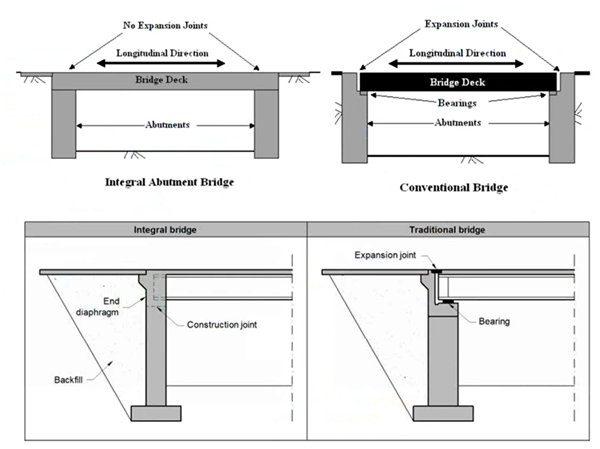
Continuous structures have proved to be more durable than simply supported decks, primarily because deck joints have allowed salty water to leak through to piers and abutments. Even BD 57/01 recommends the bridge structures to be designed as continuous over intermediate supports.
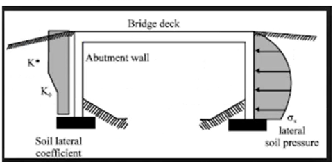
Integral bridges are subjected to many thermal cycles, repeated backward and forward movement of the abutment due to thermal expansion and contraction. This generates pressure when the bridge is expanding and is significantly higher than those that would occur with a single thermal cycle. After many cycles, this pressure tends to a maximum value with a pressure coefficient of K*. This K* is dependent on the total movement of the end of the deck from its maximum contraction position to its maximum expansion position.
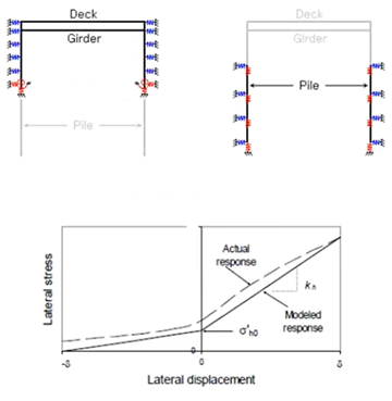
An alternative to applying the earth pressure loads is to assign appropriate spring supports to the abutment and/or piles to represent the soil properties. A method for calculation of the spring stiffness for abutments and piles published by Barry Lehane (1999, 2000, 2006) has gained significant popularity due to satisfactory performance in the prediction of the soil-structure interaction. This method considers the nonlinear behavior of soils and accounts for long-term ratcheting effects. In midas Civil this method has been adopted for automated definition of soil springs for abutments and piles.
2. Bridge Type

3. Case Study Brief.
Forder Valley Link Road (FVLR) is a proposed one-kilometer road linking William Prance Road in Derriford to the junction of Forder Valley Road and Novorossiysk Road. It will also improve accessibility for vehicles, buses, cyclists and pedestrians to key destinations.
A. Choice of structure type and backfill materials

B. Choice of Abutment Wall
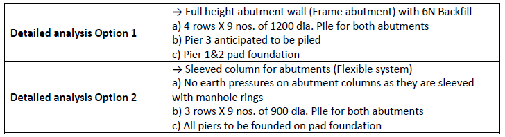
Design was finalized with Option 2 as it was structurally sound and cost-effective solution.
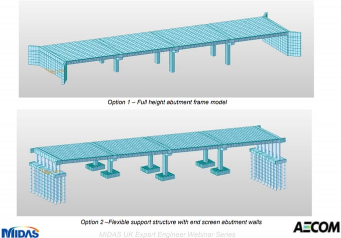
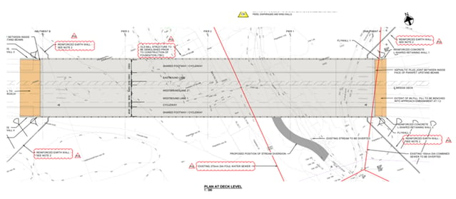
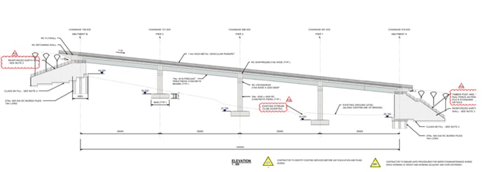
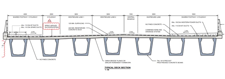
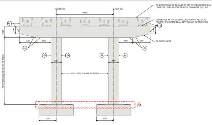
Figure 9: Abutment elevation view
4. Time-Dependent Material Properties
Shrinkage and Creep are time-dependent properties of concrete and depend on the ambient humidity, the dimensions of the element, and the composition of concrete. Creep is also influenced by the maturity of the concrete when the load is first applied and depends on the duration and magnitude of the loading. These effects are generally considered into account for the verification of serviceability limit states. The effects of shrinkage and creep should be considered at ultimate limit states only where their effects are significant, for example in the verification of ultimate limit states of stability where second-order effects are of importance. In building structures, temperature and shrinkage effects may be omitted in the global analysis provided joints are incorporated at every 30m to accommodate resulting deformations.
1. Creep Coefficient and Shrinkage Strain for construction stage analysis
Midas Civil considers the creep and shrinkage in concrete members having different maturities and compressive strength gains of concrete members as a function of time. Below Table-1 indicates the relevant code clauses that midas civil uses to consider the creep and shrinkage effects.
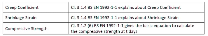
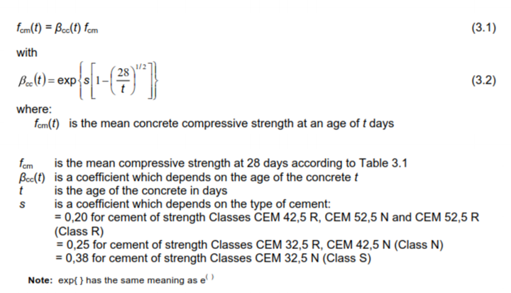
2. Compressive strength at t days for construction stage analysis
Cl. 3.1.2 (6) BS EN 1992-1-1 gives the basic equation to calculate the compressive strength at t days and are shown below:
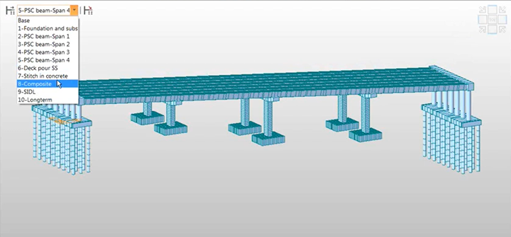
5. Construction Stages in Midas Civil
Below construction sequence of the Forder valley viaduct is simulated in the midas model:
1. Construct foundation and substructure
2. Erect span 1 beams to span 4 beams progressively
3. Concrete deck pour except at pier regions and abutment ends (simply supported condition)
4. Deck pour stitch in concrete to make the structure fully integral
5. Install surfacing
6. Service condition – Open to traffic
6. Thermal action and its application in Midas Civil
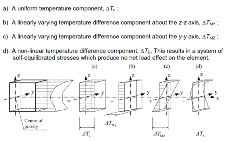
Daily and seasonal changes in shade air temperature, solar radiation, etc. will result in variations of the temperature distribution within individual elements of the structure. The magnitude of thermal effects will be dependent on local climatic conditions, together with the orientation of the structure, finishes, and overall mass. The temperature distribution within an individual structural element may be split into the following four essential components, shown in Figure 4.1 of BS EN 1995-1-5-Thermal actions
The strains and therefore any resulting stresses are dependent on the geometry and boundary conditions of the element being considered and on the physical properties of the material used.
Minimum and Maximum air shade temperatures (Tmin and Tmax) for the site shall be derived from isotherms – Figure NA.1&NA.2 NA to BS EN 1991-1-5:2003. The air shade temperatures shall be adjusted for height above sea level. Refer A.1 (1) Note 2 BS EN 1991-1-5:2003. The minimum and maximum uniform bridge temperature components Temin and Temax shall be determined using the type of bridge deck as shown in the figure below.
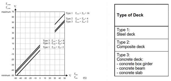
NA 2.4 BS EN 1991-1-5:2003 says the values of Temin and Temax. Shall be adjusted for deck surfacing.
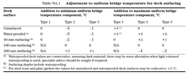
The adjusted Temin and Temax shall be considered as the final uniform temperature components that shall be applied in to the model.
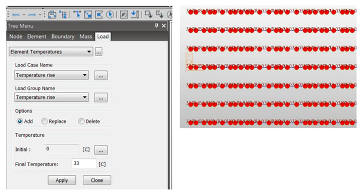
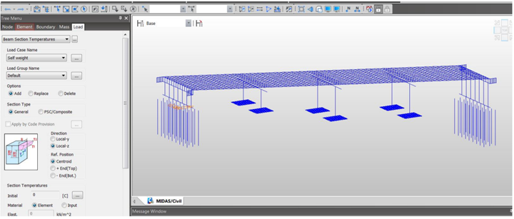
The vertical temperature component with linear effect (Approach 1) is not suitable for Forder Valley deck, as W beams are used. Not a standard rectangular section. The composite section is non-linear. Hence non-linear effect is used. The effect of the vertical temperature differences shall be considered by including a nonlinear temperature difference component as per Figure 6.2c of BS EN 1991-1-5:2003

Figure 18: BS EN 1992-1-1-5 – Temperature Gradient – code extract (Click here to zoom)
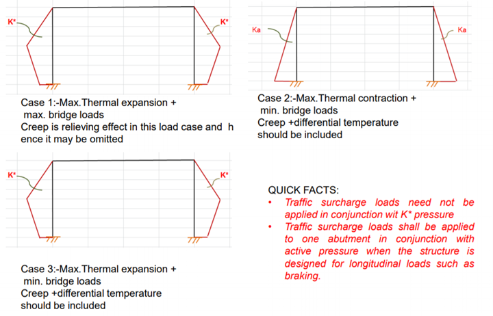
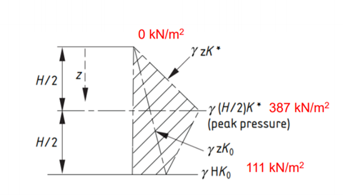
7. Earth Pressure distribution and its application in MIDAS Civil
Earth Pressure design to abutment walls comprises of below three cases:
Case-1: Maximum thermal expansion + maximum bridge loads
Case-2: Maximum thermal contraction + minimum bridge loads
Case-3: Maximum thermal expansion + minimum bridge loads
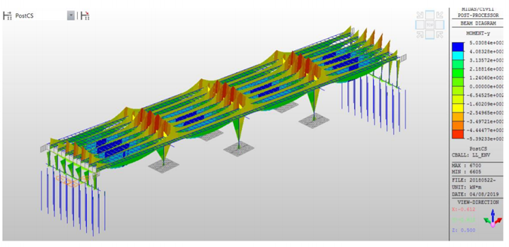
8. Global Static Analysis and Result Discussion
After analysis, the results need to be carefully chosen whether they need to be taken from construction stages or post-construction stages. Results can be extracted in tables which are excel friendly from midas Civil. Envelope load combinations can be created, and the results can be generated for these envelopes.
9. Conclusion

Webinar video link

/Photos%20of%20specialists/Mahesh%20Sankaran.jpeg)